There are three types of automotive pollutants: crankcase fumes,
exhaust gases and gasoline evaporation. The pollutants formed from these
substances fall into three categories: unburned hydrocarbons (HC), carbon
monoxide (CO), and oxides of nitrogen (NOx). The devices used to limit the
release of these pollutants into the atmosphere are commonly referred to as
emission control equipment.
Positive Crankcase Ventilation (PCV) System
OPERATION
Gasoline and Diesel Engines
The positive crankcase ventilation (PCV) valve is located on the
intake manifold below the carburetor (if so equipped), or inline with (or on)
the cylinder head cover. Routine periodic maintenance of this system basically
involves inspection of the breather hose and replacement of the PCV valve.
Common gasoline piston engine PCV
system
626 diesel PCV system
The diesel uses a very simple system designed to operate under the
extremely low manifold vacuum conditions that exist in an engine which has no
throttle valve. A breather hose connects the cylinder head cover with a fitting
in the intake manifold. The system does not require routine periodic replacement
of any part. You should inspect the breather hose occasionally and replace it if
it deteriorates. At 30,000 mile (48,309 km) intervals, or whenever removing the
cylinder head cover, you should clean the breather hose and nipples in both the
cylinder head cover and manifold in case to prevent oil or carbon clogging.
Rotary Engines
When the engine is running, small amounts of combustion gases leak
by the rotor seals and enter the rotor housings and oil pan. Since these gases
are under pressure, they tend to escape into the atmosphere. If these gases were
allowed to remain for any length of time, pressure would build up and possibly
blow out an oil seal. They would also contaminate the engine oil and cause
sludge to build up. If the gases were allowed to escape into the atmosphere,
they would pollute the air, as they contain hydrocarbons. The crankcase emission
control equipment recycles these gases back into the engine combustion chambers
where they are reburned.
Arrows indicate the flow of blow-by gases through a
rotary engine-1979-80 RX-7
In the case of the rotary engine, the word crankcase is not quite
correct, however, since the Mazda rotary engine has no crankcase in the usual
sense of the term. As a result, rotary engines do not employ a conventional PCV
valve. Instead, the "crankcase" emission control equipment for 1979-80 models
consists of a ventilation and check valve and its related hoses, which meter the
flow of fuel and air vapors through the rotor housings and oil pan. When the
engine is running, vacuum from the intake manifold opens the ventilation and
check valve. This allows blow-by gases to flow out of the rotor housings and oil
pan, and into the intake manifold where they mix with the air/fuel mixture to be
burned in the combustion chambers. When the engine is not running, the
ventilation valve is closed and blow-by gases are trapped inside the housings
until the engine is started again. The ventilation and check valve also controls
evaporative emissions, as explained later in this section.
1981-89 models do not contain a ventilation and check valve. In
its place, a check and cut valve is used.
TESTING AND REPLACEMENT
The procedures for PCV valve testing and replacement may be found
under Routine Maintenance, in Section 1.
Evaporative Emission Control System
OPERATION
Gasoline Engines
The evaporative emission control system is designed to control the
emission of gasoline vapors into the atmosphere.
Evaporative emission control system-1986-87 carbureted
323
On GLC and carbureted 323 models, the system consists of a
charcoal canister, a check and cut valve, a liquid separator (wagon only), and
purge control valves. On 626 models prior to 1988, the system consists of a
charcoal canister, a check and cut valve (or three-way check valve), purge
control valves, and on some early models, an evaporator shutter valve in the air
cleaner.
On fuel injected 323s, as well as the 1988-89 626, MX-6 and 929,
the system takes fuel vapor that is generated in the fuel tank and stores it in
the charcoal canister when the engine is not running. This fuel vapor remains in
the canister until the engine is started, at which time the fuel vapor is drawn
into the intake manifold and burned. The system on these models is made up of
the charcoal canister, purge control solenoid valves, a three-way check valve, a
vacuum switch control valve and an electronic control unit.
Rotary Engines
When raw fuel evaporates, the vapors contain hydrocarbons. To
prevent these vapors from escaping into the atmosphere, the fuel evaporative
emission control system was developed. The 1979-80 RX-7 models use a ventilation
and check valve and a charcoal canister located in the air cleaner. The 1981-85
RX-7 with carbureted engine is equipped with a conventional charcoal canister
located beside the carburetor. On these models, the flow of vapor is controlled
by a purge control valve located on top of the charcoal canister. On the 1984-89
RX-7 with fuel injection, evaporative fumes from the gas tank along with those
from the canister are regulated by the purge control valve, which introduces
them to the intake manifold. The purge control valve is located on the side of
the oil filler pipe.
Evaporative emission control system-1979-80
RX-7
Ventilation and check valve-1979-80
RX-7
On 1979-80 RX-7 models, a ventilation and check valve prevents
fuel vapors from reaching the atmosphere in the following manner: When the
engine is off, the fuel vapor from the gasoline in the fuel tank is trapped in
the fuel tank and evaporative line until it reaches a certain pressure. When
that pressure is reached, the ventilation and check valve opens, allowing fuel
vapors to pass into the rotor housings and oil pan, and mix with the blow-by
gases trapped there. The trapped gases are then fed into the charcoal canister,
along with vapors from the fuel in the carburetor float bowl. The fuel vapors
remain in the canister until the engine is started, when manifold vacuum opens
the check valve, allowing all of the vapors and blow-by gases in the rotor
housings/oil pan and charcoal canister to flow into the intake manifold. There,
the vapors and blow-by gases mix with the air/fuel mixture to be burned in the
combustion chambers.
On 1981-89 RX-7 models, a check and cut valve prevents fuel vapors
from reaching the atmosphere by performing the following functions: (1) When
vapor pressure in the fuel tank becomes too great, the valve releases the
pressure into the charcoal canister and rotor housings to prevent the tank from
bursting; (2) When vacuum pressure in the tank becomes too high, the valve
allows air into the tank to prevent it from collapsing and to insure that
sufficient fuel is pumped to the carburetor or throttle body and not drawn back
by the vacuum in the fuel tank; (3) When the vehicle is overturned, the valve
prevents fuel from flowing out of the tank. On later models, when the engine is
not running, vapors from the fuel tank are fed into the charcoal canister where
they are trapped by the purge valve. When the engine is running with the
throttle open, manifold vacuum opens the purge valve and the vapors trapped in
the canister are allowed to flow out into the throttle and dynamic chamber.
There, these vapors combine with the air/fuel mixture and pass through the
intake manifold to be burned in the combustion chambers. The bottom of the
canister contains an air filter on most models.
SYSTEM TESTING
There are several things to check if a malfunction of the
evaporative emission control system is suspected.
Piston Engines
EXCEPT 323 AND 1986-89 626/MX-6
Leaks may be traced by using an infrared hydrocarbon tester. Run the test
probe along the lines and connections. The meter will indicate the presence of
a leak by a high hydrocarbon (HC) reading. This method is much more accurate
than a visual inspection, which would indicate only the presence of a leak
large enough to pass liquid.
Leaks may be caused by any of the following, so always check these areas
when looking for them:
Defective or worn lines
Disconnected or pinched lines
Improperly routed lines
A defective check valve
If it becomes necessary to replace any of the lines used in the
evaporative emission control system, use only those hoses which are fuel
resistant or are marked EVAP.
If the fuel tank has collapsed, it may be the fault of clogged or pinched
vent lines, a defective vapor separator, or a plugged or incorrect check
valve.
CARBURETED 323
This test requires the use of a precisely calibrated pressure
gauge and a source of compressed air. If you do not have these items on hand, it
may be advisable to go to a professional for testing.
Start out by testing the No. 1 and No. 2 purge control valves, as
described in Steps 6 and 7 of the procedure for the 626/MX-6, which follows.
Check and cut valve removal-carbureted
323
Remove the air cleaner. Place a finger on top of the air vent solenoid
valve, located on top of the carburetor. Have someone turn the ignition switch
ONand OFFas you feel for operation of the solenoid. If the
solenoid does not click audibly or operate so that you can feel it, replace
the valve.
Test the water temperature valve, as described in Step 3 of the 626/MX-6
procedure. Replace the valve if it fails the test.
Remove the check and cut valve, noting that the horizontal connection goes
to the fuel tank and the vertical connection is vented to the air. Tee a
pressure gauge into the horizontal passage (normally connected to the tank).
Hold the valve horizontally for proper internal air flow. Gradually admit air
into the valve while watching the pressure. Air should start to flow through
the valve at 0.14-0.71 psi (0.98-4.9 kpa). Connect the gauge to the vertical
(vented) connection. Again, gradually admit air into the valve while watching
the pressure. It should open at 0.78-1.00 psi (5.39-6.87 kpa). Replace the
valve if it fails either test.
Test the vacuum switching valve, as described in Step 8 of the 626/MX-6
procedure.
Disconnect the vacuum delay valve. Connect the vacuum pump to the end of
the valve away from the arrow with a length of hose 40 in. (1 meter) long.
Draw a vacuum of 24 in. Hg. Then, watch as the vacuum decreases from 19.7 in.
Hg to 3.9 in. Hg, timing how long it takes. It should take 0.2-1.2 seconds. If
the valve fails the test, replace it.
FUEL INJECTED 323
Warm up the engine and allow it to run at idle speed.
Connect a voltmeter to the Yterminal of the No. 1 purge control
solenoid valve, located at the top of the canister. You should read
approximately 12V on the meter.
Disconnect the vacuum hose from the No. 1 purge control valve and place a
finger over the opening of the hose.
Checking No. 1 purge control valve-fuel injected
323
Increase the engine speed to 2,000 rpm and make sure that no air is being
sucked into the hose.
On vehicles equipped with a manual transaxle, detach the neutral switch
connector and connect a jumper wire across the terminals. On automatic
transaxle-equipped vehicles, detach the inhibitor switch connector. Check the
Yterminal voltage as described in Step 2.
Place your finger over the vacuum hose, then increase the engine speed to
2,000 rpm and make sure that no air is being sucked into the hose. If there is
a vacuum, check the engine control unit's 2P terminal, then check the No. 1
purge control solenoid and control valves, as described in Steps 7 and 8.
Checking No. 1 purge solenoid valve air flow-fuel
injected 323
To check the No. 1 purge control valve, blow through the purge control
valve from port A, as shown in the illustration, and make sure that no
air passes through it. Then, connect the vacuum pump to the purge control
valve, also as shown in the illustration. Apply a vacuum of 4.33 in. Hg to the
purge control valve, then repeat the attempt to blow air into port A.
At this time, air should pass freely through port A. If not, replace
the valve.
To check the No. 1 purge solenoid valve, disconnect the vacuum lines from
ports Aand Bon the solenoid. Detach the electrical connector
from the bottom of the solenoid. Blow into port Aand verify that air
comes out of port C. Apply battery voltage to the solenoid with a
jumper wire, then blow into port Aand verify that air passes freely
from port B. If the valve does not function as described, replace.
Proceed with the remainder of the procedure to finish the emission control
system inspection.
Fasten the neutral or inhibitor switch connector, depending on the type of
transaxle.
Disconnect the vacuum hose leading directly to the canister (not passing
through the purge valve). Disconnect the rubber hose at the canister, then
connect a vacuum source to the open end of the hose, so that air will be drawn
out of the steel pipe mounted to the car body. Operate the vacuum pump. Air
should be drawn into the pump freely. If the system holds vacuum, inspect the
pipe or the three-way check valve (located near the fuel tank) for clogging.
1986-89 626 AND MX-6
Warm up the engine, then let it idle. Disconnect the vacuum hose leading
to the purge control valve on top of the canister. Connect a vacuum gauge or
special tester 49-9200-750A, or equivalent, to the open end of the hose.
Connect a tachometer to the ignition system.
Increase the engine rpm to 2,500 and read the vacuum gauge. Vacuum must be
a minimum of 5.9 in. Hg. If the vacuum is okay, go to Step 4. Otherwise, test
the water temperature valve as described in Step 3.
Disconnect vacuum hose "B" from the No. 3 purge control
valve and plug it-1986-89 626 and MX-6
Drain some coolant out of the system, then unscrew the water temperature
valve from the intake manifold. Connect two short lengths of vacuum hose to
the valve's connection points. Immerse the lower portion of the valve in a
container of water with the vacuum hoses above the liquid level. Immerse a
suitable thermometer in the water, then heat the water to more than 130°F
(54°C) and attempt to blow air through the valve. If air passes, the valve is
okay; otherwise, replace it. Reconnect the vacuum hose.
Disconnect the vacuum hose labeled Bfrom the No. 3 purge control
valve and plug it. Then, with another length of hose, connect a vacuum gauge
to the open port in the purge control valve, as shown. Run the engine to more
than 1,500 rpm and check for vacuum. If there is no vacuum, inspect the
three-way solenoid valve, the No. 3 purge control valve and the EGR control
unit's 2P terminal. Disconnect the vacuum gauge and reconnect the vacuum hose.
Disconnect the vacuum hose leading directly into the canister (not passing
through the purge valve). Disconnect the hose at the canister, then connect a
vacuum source to the open end of the rubber hose, so that air will be drawn
out of the steel pipe mounted to the car body. Operate the vacuum pump. Air
should be drawn into the pump freely. If the system holds vacuum, inspect the
pipe or the three-way check valve (located near the fuel tank) for clogging.
Attempt to blow air into the port labeled A. No air should pass
into it.Connect the vacuum pump to the purge control valve, as shown in the
illustration. Apply a vacuum of 4.33 in. Hg to the purge control valve. Then,
repeat the attempt to blow air into A. This time, air should flow.
Otherwise, replace the purge control valve.
Blow into port "A" to begin inspection of the No. 1
purge control valve-1986-89 626 and MX-6
Testing the three-way check valve-1986-89 626 and
MX-6
Disconnect the hose referred to in Step 5 at the metal pipe, but this
time, blow into the hose with it still connected to the canister. Air should
flow freely. Otherwise, replace the No. 2 purge valve.
First, label the connecting hoses, then remove the No. 3 purge control
valve. Blow into the center port on the flat side of the valve and check for
air flow leaving the outboard port on the flat side. There should be no air
flow without vacuum being applied to the valve. Apply vacuum of 2.95 in. Hg to
the single port located on the convex side of the valve. Then, blow through
the center port again, as you did at the beginning of this step. Air should
now flow out of the outboard port. Install a new valve, if necessary, or
reinstall the old one with all hoses properly connected, according to your
labeling.
Remove the three-way check valve located on the gas tank vent line near
where the filler pipe connects with the fuel tank. Blow through Port
Aand make sure air comes out Port B. Seal off Port Band
blow again from Port A. Air should flow out of Port C. Now,
block Port Band blow through port C. Air should come out of Port
A. If the valve fails any of these tests, replace it.
The three-way solenoid valve is located at the right of the three valves
mounted on the fender well. Label, then disconnect the two hoses at the bottom
of the valve. Connect a short length of hose to the port leading into the side
of the valve near the bottom, leaving the vertical port (which discharges out
in a downward direction) open. First, blow through the hose and check for
discharge of air through the filter at the top. Then, energize the valve by
applying battery voltage to the electrical connector at the top with a jumper
wire. Now, when you blow through the hose, air should be discharged through
the port at the bottom of the valve. If the valve fails either test, replace
it.
Rotary Engines
CARBURETED MODELS
When the car is parked after operation for some distance, the fuel
in the float chamber tends to evaporate and enter the intake manifold through an
inner air vent. This, in turn, causes the fuel mixture to become too rich and
flood the engine. To prevent this chain of events, an air vent solenoid valve is
installed on the carburetor. When the engine is not running (ignition switch in
the OFFposition), a plunger attached to the air vent solenoid is pulled
out, which allows the fuel vapors in the float bowl to be fed into the charcoal
canister, where they are stored. When the engine is running (ignition switch
turned ON), the solenoid closes. This opens the air vent in the
carburetor and closes off the passage to the charcoal canister. Testing of the
air vent solenoid valve is performed as follows:
Check the air vent hose for cracking or other damage.
Disconnect the air vent hose from the ventilation pipe.
Slowly blow through the hose and make sure that air passes through the air
vent solenoid valve.
Turn the ignition switch to the ONposition.
Slowly blow through the hose; air should not pass through the air vent
solenoid. If it does, check the solenoid wiring or replace the solenoid.
FUEL INJECTED MODELS-EXCEPT 1987
Disconnect and remove the check and cut valve, as described below.
Perform the test with the valve held horizontally. Otherwise,
the weight of the valve will cause it to move out of position and close the
passage.
Testing the check and cut valve-fuel injected
RX-7
Connect a pressure gauge to the passage from the fuel tank (port
A).
Blow into the valve through port A. Check that the valve opens at
0.14-0.71 psi (0.97-4.90 kpa).
Remove the pressure gauge and connect it to the passage that vents to the
atmosphere (port B).
Blow into the valve through port Band check that the valve opens at
0.78-1.00 psi (5.38-6.89 kpa).
If the valve does not function as described, replace it.
1987 FUEL INJECTED MODELS
Disconnect and remove the check and cut valve.
Blow into the valve through port Aand make sure that air comes out
of port B.
Block port Band confirm that air comes out of port C.
Block port Band draw air through port A. Air should pass
through from port C.
If the valve does not function as described, replace it.
REMOVAL & INSTALLATION
Check and Cut Valve
Raise and safely support the rear of the vehicle.
Unfasten the hose bands and disconnect the evaporative hoses from the
check and cut valve.
Remove the check and cut valve.
Installation is the reverse of removal. Be sure to route the hoses
properly.
Exhaust Gas Recirculation System-Gasoline Engines
OPERATION
This system is used to meter a small amount of exhaust gas back
into the intake manifold to slow the combustion process, and slightly reduce the
maximum temperatures in the combustion chambers, thereby reducing nitrogen
oxides. A water temperature switch or three-way solenoid valve may stop exhaust
gas recirculation when the engine is cold. On most models, the EGR Control Valve
must be serviced periodically, and on some models, a maintenance warning system
reset. The EGR valve is by far the most sensitive part of the system, as it can
become carbon clogged.
Fuel injected 323s do not utilize an EGR system.
EGR CONTROL VALVE TESTING
If the EGR system gets clogged or the valve stem seizes due to
carbon clogging, the engine may ping even when the proper fuel is used and
ignition timing is correct. One way to check the system is to run the engine at
idle speed while placing your finger on the EGR valve diaphragm, by reaching in
under the housing at the top of the valve. Have an assistant increase the
throttle opening. The valve should open and its position should modulate as the
throttle is open and closed, adjusting for each engine operating speed and
throttle opening variation.
Place the tip of your finger as shown to check for EGR
valve function
If you doubt that the system is performing properly, the best
procedure is to test the EGR valve with the engine at idle and full manifold
vacuum applied to the valve diaphragm, as follows:
Except 1988-89 626/MX-6 and 929
Remove the air cleaner assembly.
Run the engine at idle.
On 1983-84 626 models, plug the hoses of the idle compensator,
thermosensor, and reed valves. (Consult the underhood sticker showing vacuum
hose routing to identify these).
Disconnect the vacuum sensing tube from the EGR control valve, and make
connections directly to an intake manifold tap (not to the carburetor) with a
vacuum hose.
Connect this vacuum tube to the EGR control valve. The engine should
suddenly run very roughly or stall. If it does not, clean or replace the EGR
control valve.
1988-89 626/MX-6 and 929
Grasp the rod of the EGR control valve or apply pressure to the spring
diaphragm, to make sure that it moves freely up and down and that there is
resistance from the actuating spring.
Disconnect the vacuum hose from the EGR control valve and connect a vacuum
pump to the valve.
Start the engine and run it at idle speed. Apply vacuum to the valve.
Check that the engine runs roughly or stalls when 1.6-2.4 in. Hg (40-60mm Hg)
of vacuum is applied to the valve.
If the engine does not behave as described with the specified amount of
vacuum applied, replace the EGR control valve.
EGR VALVE POSITION SENSOR TESTING
1985 626
Disconnect the position sensor connector, which leads to the
bottom of the EGR valve. Connect an ohmmeter as shown. If there is an open
circuit, the position sensor is defective and the EGR valve should be replaced.
If there is resistance, the sensor may be presumed to be okay.
Hook up an ohmmeter to the EGR valve position sensor
connector as shown-1985 626
EGR MODULATOR VALVE TESTING
You will need a source of vacuum such as a vacuum pump and a
vacuum gauge to make these tests. You may be able to disconnect and plug off the
hoses leading to this valve, then operate the engine and use engine vacuum to
make the tests. In this case, you can tee a vacuum gauge into the line which
will apply vacuum.
1986-87 323
Note the routing of all hoses leading to the modulator valve, especially
the hose which is connected to the exhaust side of the EGR valve. Remove the
EGR Modulator valve. Plug the No. 1 port, then attach a source of vacuum to
the No. 3 port.
Attach a clean hose to the exhaust gas port. Blow into the end of the hose
and maintain pressure. Apply vacuum to the No. 3 port, then seal off the
source of vacuum. Vacuum should be maintained as long as air pressure is
applied.
Stop applying air pressure. The vacuum should be released. If the valve
fails to respond properly in either Step 2 or 3, replace it.
1986-87 626
Note the routing of all hoses leading to the modulator valve, especially
the hose which is connected to the exhaust side of the EGR valve. Remove the
valve. Plug the ports numbered 2and 3. Attach a source of vacuum
to the No. 1 port.
Attach a clean hose to the exhaust gas port. Blow into the end of the hose
and maintain pressure. Apply vacuum to the No. 1 port, then seal off the
source of vacuum. Vacuum should be maintained as long as air pressure is
applied.
Stop applying air pressure. The vacuum should be released. If the valve
fails to respond properly in either Step 2 or 3, replace it.
VACUUM DELAY VALVE TESTING
1985 626
You will need a source of vacuum such as a vacuum pump and a
vacuum gauge to make these tests. You may be able to disconnect and plug the
hoses leading to this valve, then operate the engine to produce vacuum for
testing. In this case, you can tee a vacuum gauge into the line which will apply
vacuum. You will also need about four feet of vacuum line, the diameter of that
used to connect this valve into the system.
Remove the vacuum delay valve. Cut a vacuum hose of the size used to
connect this valve into the system to 40 in. (1 meter) in length. Connect the
hose to the inlet end of this valve (the arrow on the valve should point away
from the hose connection), then attach a source of vacuum and the vacuum gauge
to the other end of the hose.
Hold your thumb tightly against the open end of the valve. Apply a vacuum
of over 20 in. Hg (508mm Hg). Then, seal off the source of vacuum. Release
your thumb and watch the gauge as vacuum decreases to 4 in. Hg (102mm Hg).
This should take 1.3-2.3 seconds. If the time elapsed during the pressure drop
is outside this range, replace the valve.
REMOVAL & INSTALLATION
EGR Control Valve
On carburetor-equipped vehicles, remove the air cleaner assembly.
Disconnect the vacuum sensing tube from the EGR control valve.
Disconnect the EGR control valve-to-exhaust manifold pipe. Disconnect all
vacuum hoses.
Disconnect the pipe between the EGR control valve and the intake manifold.
On the 929, disconnect the two water hoses that are routed in front of the
valve and detach the electrical connector.
Unbolt and remove the EGR control valve.
If the old valve is to be reused, it should be cleaned with a wire brush
before installation.
To install:
Install the EGR valve with a new gasket. On the 929, fasten the electrical
connector and the two water hoses. Connect the EGR valve-to-intake manifold
pipe with a new gasket.
Connect all vacuum hoses. Connect the exhaust manifold-to-EGR valve pipe.
If applicable, install the air cleaner assembly.
Start the engine and inspect for exhaust gas leaks. On the 929, check for
water leaks also.
Exhaust Gas Recirculation System-Rotary Engine
OPERATION
1980 California RX-7s and all 1986-89 models are equipped with a
system for recirculating exhaust gases from the thermal reactor/exhaust manifold
and introducing them into the combustion chamber, in order to lower the
combustion chamber temperature and prevent the formation of oxides of nitrogen
(NOx). The system consists of an EGR valve, an EGR valve solenoid, a vacuum
switch and No. 1 water temperature sensor (1980 only).
EGR SYSTEM TESTING
1980 RX-7
Run the engine until it reaches normal operating temperature, and connect
a tachometer to the engine.
Connect a voltmeter to the brown and yellow wire in the electrical
connector of the EGR solenoid valve.
Start the engine and quickly rev it to 2,500 rpm. Current should flow to
the terminal for a few seconds and then stop.
Detach the connector from the No. 1 water temperature
switch, and connect a jumper wire-1980 RX-7
Disconnect the electrical coupler of the vacuum switch and connect a
jumper wire to both terminals in the coupler. Increase engine speed with the
throttle. Current flow to the solenoid valve should stop when the engine speed
is 2,700-3,300 rpm for manual transmission models, or 3,000-3,600 rpm for
automatic transmission models.
Increase the engine speed to 2,000 rpm with the throttle. Slowly decrease
the engine speed and record the engine speed at which the current stops
flowing to the terminal. Engine speed should be around 1,050-1,250 rpm.
Slowly increase the engine speed from idle and check the engine speed at
which the current begins to flow. Compare this figure with that recorded in
Step 5. The difference in engine speed between the two should be about 90-220
rpm.
On vehicles equipped with a manual transmission, increase the engine speed
to 2,000 rpm with the throttle. Current flow to the terminal should stop when
the idle switch lever is fully pushed up to the idle position.
Disconnect the coupler of the No.1 water temperature switch, then connect
a jumper wire to both terminals on the wiring harness, as illustrated. No
current should flow to the solenoid valve at any rpm.
Stop the engine, then start the engine with the choke knob pulled fully
out, and set the engine speed at 2,000 rpm with the choke knob. Current should
flow to the solenoid after 104-156 seconds from the time the engine was
started with the choke valve pulled out.
On vehicles with a manual transmission, set the engine speed to 2,000 rpm
using the throttle, then depress the clutch pedal and shift the transmission
into 4th and 5th gears. Current to the solenoid should stop when the gears are
engaged.
If the results of all tests are as described above, the EGR signal system
is working properly.
EGR VALVE TESTING
The EGR valve is located between the air cleaner and the bank of
solenoid valves on the engine.
Run the engine to operating temperature, then shut it off.
Disconnect the vacuum sensing tube from the EGR valve, and connect a
vacuum pump to the valve.
Start the engine and run it at idle. The engine should operate smoothly.
Apply a vacuum of 15.7 in. Hg (399mm Hg) for 1980 models, or 3.9 in. Hg
(99mm Hg) for 1986-89 models to the EGR valve. The engine should stall or
experience a sharp drop in speed if the valve is working properly.
EGR SOLENOID VALVE TESTING
1980 RX-7 (California Only)
The EGR solenoid valve is located in the bank of solenoids on the
engine and can be identified by the gray dab of paint on its body.
Disconnect the vacuum sensing tubes from the solenoid valve and the vacuum
pipe.
Blow through the solenoid valve from tube B. Air should come out of
air filter Aon the valve.
Detach the electrical connection from the EGR solenoid valve, then
activate the valve using jumper cables from the battery.
Blow through vacuum tube B. Air should come out of port C.
If the solenoid does not operate as indicated above, replace it.
1986-89 RX-7 (All Models)
The EGR solenoid valve is located in the bank of solenoids on the
engine. It supplies intake manifold vacuum to the EGR valve.
Locate the EGR valve in the engine solenoid valve bank, and disconnect the
vacuum hose from the valve (see illustration).
EGR solenoid valve location on 1986-89
RX-7
Checking EGR solenoid valve on 1986-89
RX-7
Blow into the solenoid valve through port Band place your hand
under the air filter. Air should pass freely through the valve and exit from
the air filter.
Detach the connector from the solenoid valve, then connect a 12-volt power
source and a ground to the solenoid terminals. Blow through port Bof
the valve and place your hand over the opening of port A. Air should
pass freely through the valve and exit through port A.
If the air flow is not as described above, replace the solenoid valve.
EGR Maintenance Warning System
This system is used only on rotary engine cars.
RESETTING
After the passages of the EGR valve have been cleaned with solvent
and the outlet of the valve has been wire brushed, reset the maintenance warning
system as follows:
Detach the connector, located under the left side of the dashboard.
Turn one side 180 degrees, then reconnect it.
Piston Engine Air Injection System
OPERATION
Most Mazda piston engines use the conventional air injection
system. This system uses a belt-driven vane-type pump to force air through air
injection nozzles into the exhaust manifold. The system employs a check valve
near the exhaust manifold to keep exhaust gases from traveling back into the air
lines if the air pump fails. The system also uses an air control valve which
regulates the amount of air sent to the exhaust manifold, increasing it when the
vehicle is overrunning (throttle closed at speeds beyond about 20 mph), at which
time extra fuel is admitted to the manifold.
Various models replace the air pump with a pulse-type system which
utilizes pressure waves in the exhaust system and a reed valve to pump air into
the exhaust manifold. Models not using pulse air employ a conventional air pump,
a catalytic converter, and a system which protects the converter from
overheating by interrupting air flow at high converter temperatures.
COMPONENT TESTING
Air Pump
Disconnect the hose from the air pump outlet.
Connect a pressure gauge to the outlet.
Check the drive belt for proper tension, then start and run the engine at
1,500 rpm. The gauge reading should be at least 1 psi (2.04 in. Hg/52mm Hg).
If not, replace the pump.
Reed Valve
Run the engine until it reaches normal operating temperature. Disconnect
the air hose at the reed valve.
Run the engine at idle speed, and place a finger over the inlet of the
reed valve. Air should be sucked into the valve.
Increase speed to 1,500 rpm and make sure no exhaust gas is discharged
from the reed valve inlet.
Relief Valve
Run the engine at idle.
At idle, no air should be felt at the relief valve. If air flow is felt,
replace the valve.
Increase the idle to 2,000 rpm on the 1.6L engine, or 4,000 rpm on other
engines. If air flow is felt, the valve is working properly.
Check Valve
Run the engine until it reaches normal operating temperature. Disconnect
the air hose at the check valve on the exhaust manifold.
Gradually increase the engine speed to 1,500 rpm, while carefully checking
for exhaust (hot) gas leakage from the check valve. Replace the valve if
exhaust gases are present.
Air Control Valve
Start the engine and run it at idle.
Hold a finger over the relief valve port of the air control valve.
Discharge air should be felt.
Disconnect the vacuum sensing tube from the air control valve and plug the
tube. No air should be felt at the relief port.
Air Control Valve Check Valve
Disconnect the vacuum sensing tube from the air control valve solenoid.
Blow through the vacuum tube; air should pass through the valve. Suck on
the tube; no air should pass through the valve.
COMPONENT REPLACEMENT
Air Pump
Disconnect the inlet and outlet hoses at the pump.
Unfasten the adjusting bolt and remove the drive belt.
Support the pump and remove the mounting bolts. Lift out the pump.
To install:
Lower the pump onto its mounting and install the retaining bolts.
Install the drive belt onto the pulley, then insert the adjusting bolt.
Adjust the drive belt to specification.
Connect the inlet and outlet hoses to the pump.
Air Control Valve
Disconnect the vacuum lines from the valve.
Disconnect the wiring from the valve.
Disconnect the air hoses from the valve.
Unbolt and remove the valve.
To install:
Place the valve into position and bolt it in place.
Connect the air hoses, wiring and vacuum lines to the valve.
Check Valve/Reed Valve
1978-82 MODELS
Disconnect the inlet air hose.
Unscrew the valve from the exhaust manifold.
To install:
Screw the valve into the exhaust manifold.
Connect the inlet air hose.
Pulse Air Injection System
REED VALVE INSPECTION/REPLACEMENT
This system is usually trouble-free. One symptom of improper
operation would be a high hydrocarbon emissions reading, assuming the basic
engine functions, including idle mixture adjustment, are okay. To check the reed
valves for proper function, proceed as follows:
1983-85 Models
Run the engine until it is fully warmed up. Shut off the engine and remove
the air cleaner cover and element. Get a small piece of ordinary paper.
Place the paper against the inlet port for the air injection system. Have
someone start the engine and let it idle. Air flowing into the system should
draw the paper against the air inlet.
Checking pulse air injection system-1983-84
626
Exploded view of common pulse air injection system reed
valves
Accelerate the engine until it reaches 1,500 rpm, and check that the
exhaust pressure does not force the paper away from the air inlet.
If either test is failed, replace the reed valves.
1986-87 Models
The air control valve (ACV) must be checked before the reed valves. It is
located on the side of the air cleaner. Disconnect the vacuum hose, remove the
screws and the mounting bracket, then remove the air control valve. Connect a
vacuum source to the valve, and tee in a vacuum gauge. (You can use engine
vacuum to do this, if you pinch off the vacuum line before having someone
start the engine. Be careful to gradually unpinch the line when releasing
vacuum to the gauge and valve.)
Apply vacuum gradually while watching the stem of the air control valve
and the vacuum gauge. The valve stem must start to move at 7.1-11.0 in. Hg
(180-279mm Hg). If the valve does not pass this test, replace it. If it does
pass, install the ACV back onto the air cleaner, leaving the gauge and vacuum
source connected to it.
Apply a source of vacuum to the air control valve. Vacuum must be 20 in.
Hg. (508mm Hg). If necessary, start the engine. Now, lift off the top of the
air cleaner. Check to make sure there is air flow into the ACV intake,
accessible from the inside of the air cleaner. Have someone accelerate the
engine to 2,550 rpm, then check the ACV intake again to make sure exhaust gas
is not being expelled. If either test is failed, replace the reed valve.
Rotary Engine Air Injection System
OPERATION
The air injection system used on the Mazda rotary engine differs
from the type used on a conventional piston engine in two respects:
Air is not only supplied to burn the gases in the exhaust ports, but is
also used to cool the thermal reactor/exhaust manifold.
Air injection system-1979-80
RX-7
A three-way air control valve is used in place of the conventional
anti-backfire and diverter valves. It contains an air cutout valve, a relief
valve, and a safety valve.
Air is supplied to the system by a normal vane-type air pump. The
air flows from the pump to the air control valve, where it is routed to the air
injection nozzles to cool the thermal reactor/exhaust manifold or, in the case
of a system malfunction, to the air cleaner. A check valve, located beneath the
air control valve seat, prevents the back-flow of hot exhaust gases into the air
injection system, in the event of air pressure loss.
Air injection nozzles are used to feed air into the exhaust ports,
just as in a conventional piston engine.
On 1979-80 RX-7s, an air pump feeds fresh air into the hot exhaust
gas as the gas leaves the exhaust ports. This burns the HC and CO in the exhaust
gas. The system works as follows: The air pump draws in fresh air from the air
cleaner and sends it to the air control valve, which routes it through the heat
exchanger and into the exhaust ports. Not all of the air from the pump follows
this path, however; some of the air is, at times, sent through the outer shell
of the thermal reactor to keep the reactor from reaching destructively high
temperatures. At other times, excess air from the pump is fed back into the air
cleaner by the air control valve.
Air injection system-1981-83
RX-7
Cross-section of the air control valve-1979-80
RX-7
When the air from the air pump passes through the heat exchanger,
it is pre-heated so that cold air is not pumped into the exhaust ports, which
would lower the basic temperature in the exhaust system and affect the thermal
reactor's ability to consume noxious gases. The fresh air injected into the
exhaust ports adds oxygen to the exhaust gases, and they begin to burn as they
pass into the thermal reactor. By the time the gases pass out of the thermal
reactor, the previously unburned hydrocarbons and the carbon monoxide have been
brought down to legal emission levels.
On 1981-89 RX-7s, the system used on these models replaces the
thermal reactor with two catalytic converters (No.1 monolith and No. 2 monolith)
and a reactive exhaust manifold. The system retains the air pump and the air
control valve.
Air is pulled in from the air cleaner by the air pump and sent to
the air control valve, where, according to engine operating conditions, the air
is either sent into the exhaust ports or directed down to the dual bed-type
catalyst. Excess air is sent back to the air cleaner. The air-burned
hydrocarbons and carbon monoxide ignite these unused gases in much the same way
the thermal reactor does on 1979-80 RX-7s. The air control valve sends air to
the exhaust ports, mainly during deceleration and low engine speeds when HC and
CO tend to be produced in large amounts. During this phase, the catalysts act as
backup units to insure that fewer noxious gases are produced.
At the middle engine speeds, the air control valve routes air down
to the two-bed catalyst. Air is injected through a nozzle between the two pellet
beds of the rear catalyst. When the exhaust port air is stopped, the front bed
of the rear catalyst processes oxides of nitrogen (NOx), while the rear bed,
with the help of the injected fresh air, oxidizes hydrocarbons and carbon
monoxide. The monolithic catalyst, located in front of the two-bed catalyst,
acts as a backup system for the two-bed unit.
COMPONENT TESTING
Air Pump
Check the air pump drive belt tension by applying 22 lbs. (10 kg) of
pressure halfway between the water pump and air pump pulleys. The belt should
deflect 0.28-0.35 in. (7-9mm). Adjust the belt if necessary, or replace if it
is cracked or worn.
Remove the belt and turn the pump by hand. If it has seized, the pump will
be very difficult or impossible to turn.
Test connections for the RX-7's air
pump
Disregard any chirping, squealing or rolling sounds coming from
inside the pump; these are normal when it is being turned by hand.
Check the hoses and connections for leaks. Soapy water, applied around the
area is question, is a good method of detecting leaks.
Connect a pressure gauge between the air pump and the air control valve
with a T-fitting.
After confirming the air pump's operation, disconnect
the pressure gauge from the air control valve and seal off the
T-fitting-RX-7
Plug the other hose connections (outlets) on the air control valve, as
illustrated. A gauge set which is similar to the illustrated rig (Mazda Part
No. 49-2113-010B or equivalent) is available to test the air pump.
CAUTION
Be careful not to touch the thermal reactor/exhaust
manifold; severe burns will result.
Connect a tachometer to the engine and check the idle speed. If the idle
speed is not within specifications, adjust as necessary. With the engine at
800 rpm, the pressure gauge should read 1.64 psi (3.34 in. Hg). Replace the
air pump if it is less than this.
If the air pump is not defective, leave the pressure gauge connected, but
unfasten the connections at the air control valve and plug or cap the
T-fitting, as shown, before proceeding with the next test.
Air Control Valve
1979-80 RX-7
The air control valve on 1979-80 models consists of three valves:
No. 1 relief valve, No. 2 relief valve, and an anti-afterburn valve. The No. 1
relief valve controls the flow of cooling air to the thermal reactor and is
controlled by air pump air pressure. The No. 2 relief valve controls fresh air
flow into the exhaust ports when closed, and re-routes excess fresh air back
into the air cleaner when open. The anti-afterburn valve allows additional air
into the intake manifold to prevent afterburn when the ignition is turned
OFF.
Location of the air control valve-1979-80
RX-7
Testing of the air control valve is performed as follows:
Check all hoses and vacuum sensing tubes for loose connections and damage.
Make sure the air pump drive belt is properly adjusted.
Check that the air control valve is attached to the carburetor tightly.
Disconnect the vacuum sensing tube from the relief
solenoid valve-RX-7
Check the air control valve by placing a piece of paper
in front of it-1979-80 RX-7
Connect a tachometer to the engine, and disconnect the vacuum sensing tube
from the relief solenoid valve.
The relief solenoid valve has a blue dab of paint on its
body.
Disconnect the air hose between the air cleaner and the air control valve
at the air cleaner, then start the engine and run it at idle.
Place a finger over the air hose opening and verify that air does not flow
out of the opening.
Reconnect the vacuum sensing tube to the relief solenoid valve and
gradually increase engine speed. Air should start to flow out of the air hose
when the engine speed reaches about 1,300 rpm.
Stop the engine and remove the air pipe between the air control valve and
the thermal reactor. It will be warm, so wait a few minutes and be careful.
Start the engine and run it at idle. Check to see that air does not flow
out from the air control valve by placing a piece of paper in front of the
valve, as shown in the illustration.
Increase engine speed to 4,500 rpm; air should flow out of the air control
valve.
If the results for any of these tests differ from the information
given here, the air control valve is not working properly and should probably be
replaced.
1981-83 RX-7
The air control valve consists of an air relief valve, an air
switching valve and a No. 1 anti-afterburn valve. The air relief valve controls
fresh air flow into the exhaust ports when closed, and re-routes excess fresh
air back into the air cleaner when open. The air switching valve switches the
flow of fresh air back and forth between the exhaust ports and the two-bed
catalyst according to engine demand. The anti-afterburn valve allows additional
air into the intake manifold to prevent afterburn when the ignition is turned
OFF.
Check that all solenoid valve connections are tight and that the air pump
drive belt is adjusted properly.
Make sure the air control valve is firmly attached to the engine.
Connect a tachometer to the engine. Disconnect the relief solenoid valve
vacuum sensing tube and connect the tube to a suitable vacuum source.
The relief solenoid valve has a blue dab of paint on its
body.
Disconnect the hose running from the air control valve to the air cleaner
at the air cleaner.
Start the engine and run it at idle; no air should be flowing through the
hose when the choke is off and the engine is warm.
Slowly raise the engine rpm. Air should now begin to flow through the hose
when the vacuum is removed from the sensing tube.
Reconnect the vacuum source to the relief solenoid valve vacuum sensing
tube.
Set the engine speed to 2,500 rpm with the throttle, and disconnect the
vacuum sensing tube from the switching solenoid valve (gray painted valve);
air should flow through the air hose. Air should stop flowing when this vacuum
tube is reconnected.
1984-89 RX-7
The air control valve functions to direct intake air to one of
three locations: exhaust port, main converter, or relief air silencer. The air
control valve system consists of the relief valve, switching valve and
anti-afterburn valve.
Warm up the engine to normal operating temperature. Connect a tachometer
to the engine and check/adjust the idle speed.
On 1987-89 turbocharged vehicles equipped with ABS, disconnect
the air and vacuum hoses on the air control valve from the turbocharger. Plug
the ends of the hoses before disconnecting the air control valve hose in the
next step.
Disconnect the hose that runs from the air silencer to the air control
valve at the valve.
Place a finger over the air control outlet port.
Have an assistant gradually increase the engine speed to 1,500-2,500 rpm
for 1984-89 non-turbo vehicles, or 3,750-3,850 rpm for 1986-89 turbocharged
vehicles.
On 1984-89 non-turbocharged models, locate the vacuum hose that runs
between the relief solenoid valve and the air control valve. Disconnect the
hose from the relief solenoid valve. On 1986-89 turbocharged vehicles,
unfasten the relief solenoid valve connector.
The relief solenoid valve is identified by a blue tab or blue
dab of paint on some models.
Make sure air flows from the relief solenoid valve at 1,200 rpm or
greater. Reattach the vacuum hose or the electrical connector.
Locate the split air hose that runs from the intake manifold to the check
valve. Disconnect the hose from the check valve and place a finger over the
port. Disconnect the vacuum hose from the switching solenoid valve.
Make sure air flows from the switching solenoid valve port.
If air flow is not as described, replace the air control valve.
Check Valve
The check valve prevents exhaust gases from traveling backwards
into the air pump and damaging it. There are two check valves used in the
secondary air injection system. One is installed in the intake manifold, and the
other is located inline between the intake manifold and catalytic converter.
Both check valves are tested the same way and perform the same protective
function.
Warm the engine to normal operating temperature, and connect a tachometer
to the engine.
Exhaust gas leakage at the air control valve's air
inlet indicates a defective check valve
Disconnect the hose between the air pump and the air control valve at the
air control valve. Disconnect the switching solenoid valve coupler (1981
models). If testing the catalytic converter check valve, locate the hose that
runs from the intake manifold to the converter at the rear of the intake
manifold, and disconnect it.
Slowly increase the engine speed to 1,500 rpm and watch for exhaust gas
leakage at the air inlet fitting on the air control valve. If exhaust gas is
coming out of the inlet, replace the check valve.
REMOVAL & INSTALLATION
Air Pump
If applicable, remove the air cleaner assembly from the carburetor.
Disconnect the air supply hoses from the pump.
Loosen and remove the air pump strap bolt.
Push the pump toward the engine to slacken belt tension, then remove the
drive belt from the pulley.
Air pump mounting-RX-7
Unfasten the pump securing bolts and remove the pump.
CAUTION
Do not pry on the air pump housing during removal and
do not clamp the housing in a vise once the pump has been removed. Any
type of heavy pressure applied to the housing will distort it.
To install:
Position the pump on its mounting, then install the mounting bolts. Snug
the bolts just enough to allow movement for adjustment.
Install and properly tension the drive belt by moving the air pump, then
tighten the bolts.
While applying 22 lbs. of pressure halfway between the water
pump and air pump pulleys, the belt should deflect 0.28-0.35 in.
(7-9mm).
Connect the air supply hoses.
If applicable, install the air cleaner assembly.
Air Control Valve
1979-85 CARBURETED RX-7
Remove the hot air duct.
Disconnect the air hose from the valve.
Disconnect the electrical lead from the port air solenoid valve.
Unfasten the retaining bolts and remove the valve.
To install:
Position the air control valve and secure with retaining bolts.
Connect the port solenoid valve electrical lead.
Connect the air hose to the valve and install the hot air duct.
1984-89 FUEL INJECTED RX-7
On 1984-85 models, remove the throttle chamber funnel.
Detach all solenoid valve connectors. (The number of connectors will vary
depending on the year.)
Air control valve mounting-fuel injected
RX-7
Unfasten and remove the valve.
To install:
Position the air control valve and secure with retaining bolts.
Fasten all the wiring connectors.
On 1984-85 models, install the throttle chamber funnel.
Check Valve
Remove the air control valve, as described earlier in this section.
Unscrew and remove the check valve and gasket from the manifold.
To install:
Screw the check valve into the manifold, using a new gasket.
Install the air control valve, as described above.
Air Injection Nozzle
Remove the gravel shield from underneath the car.
Remove the oil pan removal procedure, as detailed in Section
3 of this manual.
Unbolt the air injection nozzles from both ends of the rotor housing.
To install:
Attach and fasten the air injection nozzles to both ends of the rotor
housing.
Install the oil pan, as detailed in Section 3.
Fasten the gravel shield to the bottom of the car.
Thermal Reactor (Rotary Engine)
A thermal reactor is used in place of the conventional exhaust
manifold on 1979-80 RX-7 models. It is used to oxidize unburned hydrocarbons and
carbon monoxide before they can be released into the atmosphere.
Thermal reactor cooling unit
If the engine speed exceeds 4,000 rpm, or if the car is
decelerating, the air control valve diverts air into passages in the thermal
reactor housing in order to cool the reactor. (On later models equipped with
catalytic converters, air flow into the reaction chamber is cut off under these
conditions.)
A one-way valve prevents hot exhaust gases from flowing back into
the air injection system. The valve is located at the reactor air intake.
INSPECTION
CAUTION
Perform thermal reactor inspection only after the
reactor has cooled sufficiently to eliminate the danger of being severely
burned.
Examine the reactor housing for cracks or other signs of damage.
Remove the air supply hose from the one-way valve. Insert a screwdriver
into the valve and test the butterfly for smooth operation. Replace the valve
if necessary.
If the valve is functioning properly, reconnect the hose to it.
Remember to check the components of the air injection system
which are related to the thermal reactor.
Check the thermal reactor's butterfly valve for smooth
operation
REMOVAL & INSTALLATION
Thermal reactor removal and installation procedures are given in
Section 3 of this manual.
Piston Engine Deceleration Control System
ADJUSTMENTS
Vacuum Throttle Opener
1978 GLC
Connect a tachometer to the engine. Run the engine until hot, then shut it
OFFand remove the air cleaner assembly.
Adjusting the vacuum throttle opener system-1978
GLC
Disconnect/plug the anti-afterburn valve vacuum line,
then tee a gauge between the intake manifold and vacuum control valve-1978
GLC
Disconnect the vacuum sensing tube Ffrom the servo diaphragm, then
connect a vacuum hose between the vacuum tap on the intake manifold and the
diaphragm.
Disconnect the vacuum line that runs from the carburetor to the
distributor at the distributor, and plug the open end.
Start the engine and read the tachometer. Engine speed should be
1,300-1,500 rpm. If the speed is not to specification, turn the throttle
opener adjusting screw to bring engine speed within the range.
Reconnect the distributor and servo diaphragm vacuum lines, then
disconnect and plug the vacuum line going to the anti-afterburn valve.
Disconnect the vacuum line going from the intake manifold to the vacuum
control valve, and tee in a vacuum gauge as shown.
Start the engine and accelerate to 3,000 rpm. Watch the vacuum gauge and
release the throttle. After a rapid rise in vacuum, the gauge reading should
stabilize at 22.0-22.8 in. Hg (559-579mm Hg) for a few seconds while the
system gradually closes the throttle, then drop off.
If vacuum does not stabilize in the right range, loosen the locknut and
turn the adjusting screw in the end of the vacuum control valve until vacuum
is in the specified range. Turn the screw clockwise to increase the vacuum
reading, and counterclockwise to decrease it.
Tighten the locknut, then restore all vacuum connections. Install the air
cleaner assembly and remove the tachometer.
Servo Diaphragm
Connect a tachometer to the engine.
Run the engine at idle to normal operating temperature.
Stop the engine and remove the air cleaner assembly.
Disconnect the vacuum sensing tube at the servo diaphragm.
Connect the inlet manifold and the servo diaphragm with a suitable tube,
so that the inlet manifold vacuum can be led directly to the servo diaphragm.
Disconnect the vacuum sensing tube (which runs from the carburetor to the
distributor) at the distributor, then plug the tube.
Start the engine and check to see that the engine speed increases to
1,100-1,300 rpm (GLC) or 1,000-1,200 rpm (626).
Turn the throttle positioner adjuster screw in or out, as required, to
adjust to specifications.
COMPONENT TESTING
Three-Way Solenoid Valve
Disconnect the vacuum sensing tube Afrom the servo diaphragm.
Disconnect the vacuum sensing tube Bfrom the three-way solenoid
valve.
Three-way solenoid valve check with the ignition switch
ON
Three-way solenoid valve check with the ignition switch
OFF
Detach the connector (blue/black wire) from the engine speed switch and
ground the three-way solenoid valve using a jumper wire.
Turn the ignition switch ON.
Blow into the three-way solenoid valve through tube Aand make sure
air comes out of the valve's filter.
Turn the ignition switch OFF.
Blow into the valve through tube Aand make sure air comes out of
port A.
Replace the three-way solenoid valve if it does not operate properly.
Engine Speed Switch
Detach the engine speed switch connector.
Attach a voltmeter to the connector.
Engine speed switch check
Increase the engine speed to 2,000 rpm, then slowly decrease the engine
speed.
Record the engine speed at which the current flows to the circuit. The
engine speed should be 1,600-1,800 rpm (California AT) and 1,400-1,600 rpm
(Canada MT).
Slowly increase the engine speed again and record the engine speed at
which the current does not flow to the circuit. The difference between the
engine speed recorded in steps 4 and 5 should be 150-250 rpm.
Replace the engine speed switch if the rpm specifications are not met.
Rotary Engine Deceleration Control System
OPERATION
RX-7 With Carburetor
The deceleration control system on manual transmission models
consists of the anti-afterburn valve (two used on 1981 and later models), the
dashpot and its delay valve, and the coasting valve. On automatic transmission
models, only the anti-afterburn valve is used.
The single (or primary) anti-afterburn valve is part of the air
control valve. Please refer to the preceding Air Injection System coverage for
additional information.
On 1981 and later models, the second anti-afterburn valve is
located to the rear of the carburetor. It controls air intake to the rear rotor,
while the anti-afterburn valve (in the air control valve) controls air intake to
the front rotor.
The dashpot acts to slow down the closing speed of the throttle
valve in the carburetor when the accelerator pedal is released. This helps
prevent engine misfire. The dashpot also acts as an emission control device.
The coasting valve allows additional air into the intake manifold
to prevent engine misfire during deceleration at engine speeds over 1,150 rpm.
It is regulated by the control unit and the idle switch on the carburetor.
RX-7 With Fuel Injection
The deceleration control system on fuel injected RX-7s consists of
a fuel cut-off circuit, throttle sensor, anti-afterburn valve and dashpot.
The fuel cut-off circuit stops flow to the fuel injectors while
decelerating during certain engine speed ranges.
The throttle sensor measures the opening angle of the primary
throttle valve; it sends this information to the control unit, which determines
the proper air/fuel mixture needed by the engine during deceleration.
The anti-afterburn valve is an integral component of the air
control valve. The valve feeds fresh air into the rear port during deceleration.
The dashpot gradually shuts the throttle valve during
deceleration.
COMPONENT TESTING
These systems are highly complex and are covered by an extended
warranty. Therefore, only simple adjustments are included here.
Anti-Afterburn Valve
1979-80 RX-7
Check all hoses and vacuum sensing tubes for improper connections and
signs of wear; replace as necessary.
Disconnect the hose which runs from the air control valve to the air
cleaner at the air cleaner assembly.
Air control valve with its integral anti-afterburn
valve-1979 RX-7 shown
Disconnect the vacuum sensing tube from the relief solenoid valve, which
can be identified by the blue spot of paint on its body.
Start the engine and run it at idle. Place your finger over the
disconnected hose to the air cleaner; no vacuum should be present.
Detach the electrical connection of the anti-afterburn solenoid valve;
vacuum should now be present in the hose. If not, the anti-afterburn valve,
its solenoid valve or its vacuum lines are defective and must be replaced.
1981-85 RX-7 WITH CARBURETOR
Test the No. 1 anti-afterburn valve as follows:
Warm up the engine and run it at idle speed.
Locate the hose that runs between the air control valve and the air pump.
Disconnect the hose at the air pump.
Place a finger over the opening of the air hose and check that no air is
sucked into the hose at idle speed.
Have an assistant increase the idle speed to just over 3,000 rpm, then
quickly release the accelerator pedal. Make sure air is sucked into the hose
for a few seconds while the engine is decelerating. If not, replace the air
control valve.
Test the No. 2 anti-afterburn valve as follows:
Warm up the engine and run it at idle speed.
Locate the hose that runs between the air cleaner and the No. 2
anti-afterburn valve. Disconnect the hose at the air cleaner.
Place a finger over the opening of the air hose and check that no air is
sucked into the hose at idle speed.
Have an assistant increase the idle speed to just over 3,000 rpm, then
quickly release the accelerator pedal. Make sure air is sucked into the hose
for a few seconds while the engine is decelerating. If not, replace the air
control valve.
1984-89 RX-7 WITH FUEL INJECTION
Warm up the engine and run it at idle speed.
Locate the hose that runs between the air control valve and the air pump.
Disconnect the hose at the air pump.
Place a finger over the opening of the air hose and check that no air is
sucked into the hose at idle speed.
Have an assistant increase the idle speed to just over 3,000 rpm, then
quickly release the accelerator pedal. Make sure air is sucked into the hose
for a few seconds while the engine is decelerating. If not, replace the air
control valve.
Dashpot
1979 RX-7
This test procedure applies only to vehicles equipped with a
manual transmission.
Remove the air cleaner assembly.
Check all vacuum hoses for tears and/or deterioration. Replace as
required.
Make sure the dashpot plunger rod does not keep the throttle lever from
returning to its idle stop when closed.
A dashpot affects closing of the throttle valve on some
RX-7s
Quickly operate the throttle lever; the dashpot plunger rod should quickly
extend.
Release the throttle lever; the plunger rod on the dashpot should slow its
return to the idle position.
Connect a tachometer to the engine.
Start and run the engine until it reaches normal operating temperature.
Make sure the idle speed is within specifications; adjust as necessary.
Disconnect the vacuum sensing tube from the top of the dashpot and move
the throttle lever away from the dashpot plunger rod. Close the vacuum inlet
at the top of the dashpot with your finger.
Release the throttle lever and check the engine speed at which the dashpot
stops moving after it has been pushed in by the throttle lever. This speed
should be 1,650-1,850 rpm. If not, loosen the locknut on the dashpot and
adjust by turning the dashpot body. Repeat Step 9 to verify the adjustment.
1980-85 RX-7
On 1980-82 models, this test procedure applies only to vehicles
equipped with a manual transmission.
Remove the air cleaner assembly (carbureted models only).
Check to see that the dashpot does not keep the throttle lever from
returning to the idle stop.
Quickly operate the throttle lever fully; when the throttle lever is open,
the dashpot plunger rod should quickly extend.
Release the throttle lever. The lever should quickly snap closed until it
hits the dashpot plunger rod, then slowly close until it reaches its stop.
Connect a tachometer to the engine. Run the engine until it reaches normal
operating temperature, then make sure the idle speed is correct.
Move the throttle lever until it is away from the dashpot plunger rod.
Slowly close the throttle lever and note the engine speed when the
throttle lever just touches the dashpot plunger rod. If engine speed is not
3,500-3,900 rpm for 1980 models, 3,800-4,200 rpm for 1981-85 carbureted
models, or 2,350-2,650 rpm for fuel injected models, loosen the locknut and
adjust the dashpot by turning it until its plunger rod is in the correct
position.
1986-89 RX-7
On turbocharged models, drain the cooling system and remove the
intercooler.
Manually open the throttle valve fully, then push the dashpot actuating
rod with your finger; verify that the rod retracts slowly into the dashpot.
Release the rod and check that it returns quickly to its original
position.
If the dashpot does not operate as described, adjust or replace it.
(Dashpot adjustment is described later in this section.)
Coasting Valve
1979-80 RX-7 WITH MANUAL TRANSMISSION
The coasting valve allows additional air into the intake manifold
to prevent engine misfire during deceleration at engine speeds over 1,150 rpm.
It is regulated by the engine control unit and the idle switch on the
carburetor.
Connect a tachometer to the engine.
Warm the engine to its normal operating temperature.
Detach the electrical connection from the coasting valve, then attach a
voltmeter to the harness side of the connection. Disconnect the vacuum sensing
tube from the dashpot diaphragm on 1979 models.
Start the engine and increase the engine speed to 3,000 rpm, using the
throttle. Quickly release the throttle lever; current flow should stop when
the engine speed falls below 1,050-1,250 rpm (1,000-1,200 rpm on Canadian
models). Shut off the engine.
Disconnect the voltmeter, then detach the air hose (running from the
coasting valve to the air cleaner) at the air cleaner assembly.
Do not yet reconnect the coasting valve electrical
connection.
Start the engine. There should be no vacuum at the air hose. Activate the
coasting valve by attaching jumper wires to its electrical connection from the
battery; when the engine is running, vacuum should be present in the air hose.
Testing the coasting valve-1979-80
RX-7
1981-85 CARBURETED RX-7
Warm up the engine to its normal operating temperature.
Disconnect the hose from the coasting valve to the air cleaner at the air
cleaner assembly.
With the engine running at idle, place a finger over the hose opening and
verify that air is not drawn into the hose.
Detach the connector from the shutter solenoid valve; air should be drawn
into the disconnected hose as the idle roughens. At that same moment, check
that the coasting valve rod retracts into the coasting valve approximately 0.4
in. (10mm).
ADJUSTMENTS
Throttle Positioner
Disconnect the wiring from the coasting valve solenoid, and connect the
solenoid directly to the car battery.
Loosen the locknut on the solenoid adjuster.
Rotate the adjuster until an idle speed of 900-1,000 rpm is obtained after
releasing the throttle from an engine speed of 2,000 rpm.
Tighten the locknut carefully once the proper idle speed has been
obtained.
Disconnect the jumper wires from the battery, then reattach the coasting
valve solenoid's electrical connector.
As soon as the solenoid is disconnected from the battery, idle
speed should drop to 800 rpm.
Idle Switch
Warm up the engine until the water temperature is at least 159°F (71°C).
Make sure that the mixture and idle speed are adjusted properly.
Adjust the idle speed to 1,075-1,100 rpm (manual transmission) or
1,200-1,300 rpm (automatic transmission), by rotating the throttle adjusting
screw.
Rotate the idle switch adjusting screw until the switch changes from the
OFF to ON position.
Slowly turn the idle switch adjusting screw back to the point where the
switch just changes from ON to OFF.
Turn the throttle screw back so that the engine returns to normal idle.
Be sure that the idle switch turns ON when the idle speed is
still above 1,000 rpm.
Dashpot
1986-89 NON-TURBO RX-7
Start the engine and allow it to warm up to normal operating temperature
at idle speed.
Connect a tachometer to the engine and increase the engine speed to 3,000
rpm.
Slowly decrease the engine speed and verify that the dashpot actuating rod
makes contact with the throttle lever at 2,700-3,100 rpm.
To adjust the dashpot, loosen the locknut and rotate the dashpot body
clockwise or counterclockwise until the rod makes contact with the lever at
the specified rpm.
1986-89 RX-7 TURBO
Drain the cooling system and remove the intercooler.
Detach the throttle sensor connector.
Checking dashpot resistance-1986-89 RX-7
turbo
Attach an ohmmeter to terminals Aand Bof the throttle sensor
connector, as shown in the illustration. Set the meter to the 1000x scale.
Manually separate the dashpot actuating rod from the throttle lever and
observe the reading on the meter. As the rod and lever separate, the
resistance should be 1.8-3.8 kilohms. If the reading is not as specified,
adjust by loosening the locknut on top of the dashpot and rotating the dashpot
body either clockwise or counterclockwise, until the proper resistance is
obtained. Once the adjustment is complete, tighten the locknut.
Oxygen Sensor
As part of the vehicle's closed loop (or feedback control) system,
the oxygen sensor monitors the density of oxygen in the exhaust gas. The sensor
consists of a closed-end tube made of ceramic zirconia and other components.
Porous platinum electrodes cover the tube's inner and outer surfaces. The tube's
outer surface is exposed to the exhaust gases in the exhaust manifold (or, if so
equipped, just beyond the turbocharger). After detecting the amount of oxygen in
the exhaust gas, the oxygen sensor outputs an electrical signal to the engine
control unit.
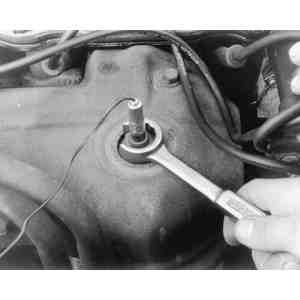
REMOVAL & INSTALLATION
Gasoline Engines
The oxygen sensor is installed in the exhaust manifold (or the
front catalytic converter on turbocharged vehicles), and is removed in similar
manner to a spark plug. (Unlike spark plug removal, use an open-end wrench to
avoid interference with the electrical lead.)
Disconnect the negative battery cable.
Unfasten the sensor's electrical connector.
Use an open-end wrench to remove and install the oxygen
sensor
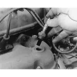
Handle the oxygen sensor very carefully, be sure not to
damage the insulator
Using the correct size wrench, loosen and unscrew the oxygen sensor. If so
equipped, be sure to also remove the crush ring gasket with the sensor.
Exercise care when handling the sensor; do not drop or handle
it roughly. The electrical connector and louvered end must be kept free of
grease and dirt.
Clean the threads of the sensor and its mounting location.
To install:
If applicable, make sure that the crush ring gasket is threaded onto the
sensor.
Coat the threads of the sensor with an anti-sieze compound. Be careful to
coat only the threads of the sensor; do not get compound on the sensor itself.
Screw the sensor and gasket into its mounting location and torque to
specification.