Run the engine until it reaches operating temperature (coil must be hot).
Disconnect the high tension lead from the coil tower.
Measure primary resistance with an ohmmeter, connecting between the coil's
negative (-) and positive (+) primary terminals. Resistance should be
1.15-1.28 ohms (GLC) or 0.9-1.15 ohms (626).
Measure secondary resistance, connecting the ohmmeter between the coil
tower and the positive (+) primary terminal. Resistance should be 13,500 ohms
(GLC) or 7,000 ohms (626).
Replace the coil if either resistance is incorrect by more than 10%.
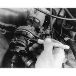
Test the coil primary resistance as
shown
Test the coil secondary resistance as
shown
1982-89 VEHICLES
Connect an ohmmeter, set to the x 1 scale, to the positive (+) and
negative (-) primary terminals of the coil. The coil should have good
continuity; resistance should be approximately 1.0-1.3 ohms on all models
except the 1988-89 626/MX-6 turbo and 929. Resistance on the 1988-89 626/MX-6
turbo and 929 should be 0.72-0.88 ohms.
Checking ignition coil primary resistance-1986-89 323,
626/MX-6 and 929
Disconnect the high tension wire from the coil. Connect the ohmmeter to
the positive (+) coil terminal and the metallic connector inside the coil
tower. Set the ohmmeter to the x 1000 scale. Resistance must be 10,000-30,000
ohms, except on the following:
1986-89 323: 6,000-30,000 ohms
1988-89 626/MX-6 (non-turbo): 7,000-9,700 ohms
1988-89 626/MX-6 (turbo): 10,300-13,900 ohms
Checking ignition coil secondary resistance-1986-89
323, 626/MX-6 and 929
Checking ignition coil insulation-1986-89 323, 626/MX-6
and 929
You can also check for bad coil insulation by measuring the resistance
between the coil negative (-) primary connection and the metal body (housing)
of the coil. If resistance is less than 10,000 ohms, replace the coil.
This test may not be entirely satisfactory unless you have a
tester that produces 500 volts. If the tests below do not reveal the problem
and, especially, if operating the engine at night produces some bluish sparks
around the coil, you may want to remove the coil and have it tested at a
diagnostic center.
If the coil resistances are not as specified, replace the coil.
If the coil tests OK, replace the igniter and pickup coil. However, you
should make sure before doing this work that there are no basic maintenance
problems in the secondary circuit of the system, since it is often impossible
to return electrical parts. We suggest that before you replace the igniter and
pickup coil, you carefully inspect the cap and rotor for carbon tracks or
cracks. Also, disconnect the wires and measure their resistance with an
ohmmeter. Resistance should be 16,000 ohms per length of 3.28 feet (1 meter).
Also, check for cracks in the insulation. Replace secondary parts as
inspection/testing deems necessary before replacing the igniter and pickup
coil.
RX-7
1979-85 VEHICLES
The coil(s) must be at normal operating temperature to perform
this test, so either start the engine or turn the ignition ON until the coils
heat up. If one or both coils won't get hot, check your wiring or try to
substitute coil(s).
Check the leading ignition first. Remove the high tension cable from its
center tower and connect the leads of an ohmmeter to the two side terminals.
Resistance should be 1.22-1.48 ohms.
Test the trailing coil in the same manner. It should also give a reading
of 1.22-1.48 ohms.
If either reading is out of specification, replace the coil(s).
1986-89 VEHICLES
This testing procedure covers both the leading and trailing
side ignition coils; however, the coils differ in appearance and design. On the
trailing side coil, there are two sets of terminals that require resistance
checks, whereas the leading side has only one set. When checking the coil
resistance, be sure to distinguish between the two coils.
Checking the leading ignition coil resistance-1986-89
RX-7
Checking the trailing ignition coil resistance-1986-89
RX-7. Note the two sets of terminals to be
checked
Disconnect the negative battery cable.
Set your ohmmeter to the x 1 scale, then connect the ohmmeter probes to
the positive (+) and negative (-) coil terminals. On the trailing side, test
both sets of terminals.
If the resistance is above 1 ohm, replace the coil.
CHECKING EXTERNAL RESISTOR
1979 RX-7 Only
The external resistor block is located inside the engine
compartment on the driver's side strut pod. The external resistor modifies the
current going into the positive primary terminal of the ignition coil. This
allows the coil to be constructed so that a strong spark is generated at high
engine speeds.
All of the electrical terminals for the trailing ignition coil
have light colored protective caps, while all leading coil terminals have dark
colored caps.
Connect the leads of an ohmmeter to the trailing coil side of the
resistor (the side with the light colored caps). Resistance should be 1.26-1.54
ohms. Repeat the test on the leading side of the resistor (the side with dark
caps). The reading should be the same as for the trailing side. If the reading
is not within or close to this range, replace the resistor.
Checking the external resistor (left) and the leading
ignition coil's primary resistance (right)-1979
RX-7
REMOVAL & INSTALLATION
Except RX-7
Most Mazda coils are located on the fender well (rear wheel drive
cars) or the front engine compartment panel (front wheel drive cars) to keep
them away from engine heat. On some 1986-89 models, the ignition coil is bolted
to the air cleaner assembly.
Disconnect the negative battery cable and make sure the ignition switch is
OFF.
Remove the protective boot from the top of the coil, if necessary, by
sliding it back on the coil-to-distributor wire.
Carefully pull the high tension wire out of the coil, twisting it gently
as near as possible to the tower to get it started.
Note the routing and colors of the primary wires, then remove the nuts and
lockwashers, retaining all parts for installation. Clean the primary terminals
with fine grit sandpaper, if necessary, to ensure a clean connection. Then,
loosen the through-bolt or bolts which clamp the coil in place and slide the
coil out of its mount.
To install:
Install the new coil in exact reverse order, making sure the primary (+
and -) connections are clean and tight. Ensure also that the
coil-to-distributor wire is fully seated in the tower and that the protective
boot is fully installed on the outside of the tower.
RX-7-1979-85
Disconnect the negative battery cable.
Disconnect the negative (-) coil terminal couplers.
Loosen the nuts on the positive (+) terminals and remove the wires.
Label, then remove, the wires from the leading and trailing coils.
Remove the three bracket bolts and coil assembly.
To install:
Position the new coil assembly onto its mounting and attach it with the
three bracket bolts.
Connect the wires to the leading and trailing coils.
Place the wires on the positive (+) coil terminals and install the
terminal post nuts.
Connect the negative (-) terminal couplers.
Connect the negative battery cable.
RX-7-1986-89
The 1986-89 RX-7 leading and trailing ignition coils each have
a built-in igniter.
LEADING SIDE
Disconnect the negative battery cable.
Label the wires for identification.
Loosen the nuts and disconnect the primary wires from the coil/igniter.
Disconnect the 2-prong connector.
Remove the bracket bolts and coil/igniter assembly.
Installation is the reverse of removal.
TRAILING SIDE
Disconnect the negative battery cable.
Label the wires for identification.
Loosen the nuts and disconnect the (B) and (L) primary wires from the
coil/igniter.
Disconnect the 2 and 4-prong connectors.
Remove the bracket bolts and coil assembly.
Installation is the reverse of removal.
Igniter Module
On the 929, the igniter module is a separate, replaceable
component.
REMOVAL & INSTALLATION
929
The igniter module is located next to the ignition coil on the
driver's side of the engine compartment.
Igniter mounting-929
Disengage the harness connector from the top of the igniter.
Remove the two attaching screws and remove the ignitor.
Install the new igniter and secure it with the two attaching screws.
Engage the harness connector.
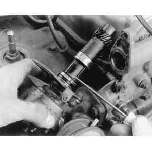
Distributor
REMOVAL & INSTALLATION
Piston Engines
1978-85 ALL MODELS
Unfasten the clips or remove the screws which hold the distributor cap to
the top of the distributor, then remove the cap. Note the location of the wire
going to the No. 1 cylinder (the front cylinder on rear drive cars, or the
cylinder on the left side of the car on front drive cars) where it enters the
cap.
Rotate the engine with the starter, or by using a socket wrench on the
bolt retaining the crankshaft pulley (turning in the normal direction of
rotation), until the timing mark on the pulley is aligned with the pin on the
front cover. Check to see if the contact on the rotor is pointing toward the
No. 1 spark plug wire's cap location (tower). If the rotor is half a turn away
from the No. 1 plug wire, turn the crankshaft ahead one full rotation until
the timing mark is again aligned with the pin.
Matchmark the distributor body and rotor with the
cylinder head or retaining bracket
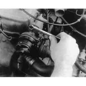
Use the correct size box wrench to remove the
retaining/adjusting bolt
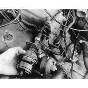
Withdraw the distributor assembly from the
engine
Check the condition of the
O-ring
Disconnect the vacuum advance or advance/retard line(s) at the advance
unit, and disconnect the primary wire or wires at the connector near the
distributor.
Matchmark the distributor body and rotor with the cylinder head or
retaining bracket.
Remove the retaining/adjusting bolt, then pull the distributor out of the
engine. If so equipped, remove the O-ring.
For easier installation, avoid rotating the engine with the
distributor removed.
To install:
If the engine has been rotated while the distributor was out,
it will be necessary to turn the crankshaft until the point where the No. 1
cylinder is about to fire. This is known as Top Dead Center (TDC). To do this,
remove the No. 1 spark plug and rotate the engine until you can feel compression
building (with your finger over the spark plug hole). Then, rotate the engine
until the timing mark on the front pulley is aligned with the pin on the front
cover, and proceed with Step 6.
Lightly oil and install a new O-ring near the top of the distributor shaft
on applicable 1981-85 models.
Lubricate the O-ring on 1982-85
distributors
On FWD GLC, the distributor engages a notch in the rear
of the camshaft. Do not remove the seal block (not shown) at the rear of
the valve cover
Lightly oil the distributor drive gear, then align the dimple on the gear
with the mark cast into the base of the distributor body by rotating the
shaft. Being careful not to rotate the shaft, insert the distributor back into
the cylinder head with the distributor body and cylinder head matchmarks
aligned.
The distributor used on front wheel drive GLCs does not have a
drive gear. Instead, it has a blade which inserts into a groove in the rear end
of the camshaft.
Install the mounting bolt, but do not tighten it.
Install the distributor cap, then reconnect the vacuum advance line and
primary connector.
If the distributor has ignition points and they have been disturbed, set
the dwell as described in Section 2.
Set the ignition timing, as described in Section 2.
1986-89 323
Tag and disconnect the spark plug wires from the distributor cap, then
route them off to the side and out of the way.
If the same distributor cap is to be reinstalled, remove the
cap with the wires attached.
Disconnect the vacuum hose(s) and the electrical connector from the
distributor.
Distributor mounting-1986-89 323
non-turbo
Distributor mounting-1988-89 323
turbo
Distributor blade and rotor alignment-1986-89 323
non-turbo
On 1988-89 turbocharged 323s, align the distributor
blade with the groove in the housing
Distributor components-1986-89 323
non-turbo
Distributor components-1988-89 323
turbo
Rotate the engine so that the No. 1 piston is at Top Dead Center (TDC) as
follows:
Engage the starter motor, or turn a socket wrench (in the direction of
normal engine rotation) on the bolt retaining the crankshaft pulley, until
the timing mark on the pulley is aligned with the pin on the front cover.
Check to see if the contact on the rotor is pointing toward the No. 1
spark plug wire's cap location (tower). If the rotor is half a turn away
from the No. 1 plug wire, turn the crankshaft ahead one full rotation until
the timing mark is again aligned with the pin.
Remove the distributor hold-down bolt(s) and withdraw the distributor from
the cylinder head.
Remove the O-ring seal and discard it.
For easier installation, avoid rotating the engine with the
distributor removed.
To install:
If the engine has been rotated while the distributor was out,
it will be necessary to turn the crankshaft until the point where the No. 1
cylinder is at TDC. To do this, remove the No. 1 spark plug and rotate the
engine until you can feel compression building (with your finger over the spark
plug hole). Then, rotate the engine until the timing mark on the front pulley is
aligned with the pin on the front cover, and proceed with Step 6.
Coat the new O-ring seal with a light film of clean engine oil and install
it into the cylinder head opening.
Make sure that the number one piston is at top dead center
before installing the distributor.
On non-turbocharged engines, turn the distributor blade so that it aligns
with the small oil holes in the bottom of the distributor. On turbocharged
engines, align the distributor blade with the grooved matchmark on the body.
Install the distributor, then engage the wiring connector, vacuum hose(s)
and spark plug wires.
Set the ignition timing, as described in Section 2.
1986-89 626 AND MX-6
Tag and disconnect the spark plug wires from the distributor cap, then
route them off to the side and out of the way.
If the same distributor cap is to be reinstalled, remove the
cap with the wires attached.
On non-turbocharged engines, disconnect the vacuum hoses and wiring. On
turbocharged engines, disconnect the electrical coupler.
Exploded view of the distributor used on the 1986-87
turbocharged 626
Distributor blade and rotor alignment-1988-89
626/MX-6
Rotate the engine so that the No. 1 piston is at Top Dead Center (TDC) as
follows:
Engage the starter motor, or turn a socket wrench on the bolt retaining
the crankshaft pulley (in the normal direction of engine rotation), until
the timing mark on the pulley is aligned with the pin on the front cover.
Check to see if the contact on the rotor is pointing toward the No. 1
spark plug wire's cap location (tower). If the rotor is half a turn away
from the No. 1 plug wire, turn the crankshaft ahead one full rotation until
the timing mark is again aligned with the pin.
Loosen the lockbolt(s) and remove the distributor.
Remove and discard the O-ring from the coupling shaft.
WARNING
For easier installation, do not rotate the engine with
the distributor removed, unless necessary.
To install:
If the engine has been rotated while the distributor was out,
it will be necessary to turn the crankshaft until the point where the No. 1
cylinder is at TDC. To do this, remove the No. 1 spark plug and rotate the
engine until you can feel compression building (with your finger over the spark
plug hole). Then, rotate the engine until the timing mark on the front pulley is
aligned with the pin on the front cover, and proceed with Step 6.
Install a new O-ring onto the coupling shaft, then apply a coat of clean
engine oil to the O-ring and to the driven gear.
On 1986-87 models, first align the dimple on the distributor drive gear
with the mark cast into the base of the distributor body by rotating the
shaft.
On 1988-89 models, align the shaft coupling blade with the alignment marks
on the distributor body, then turn the distributor over and check that the
rotor is aligned as shown in the illustration.
Install the distributor and engage the wiring connector, vacuum hose(s) ad
spark plug wires.
Set the ignition timing, as described in Section 2.
929
Tag and disconnect the spark plug wires from the distributor cap, then
route them off to the side and out of the way.
If the same distributor cap is to be reinstalled, remove the
cap with the wires attached.
Disengage the distributor electrical connector.
Distributor components-929
Distributor drive gear alignment
marks-929
Rotate the engine so that the No. 1 piston is at Top Dead Center (TDC) as
follows:
Engage the starter motor, or turn a socket wrench on the bolt retaining
the crankshaft pulley (in the normal direction of engine rotation), until
the yellow mark on the pulley is aligned with the "T" mark on the timing
scale.
Check to see if the contact on the rotor is pointing toward the No. 1
spark plug wire's cap location (tower). If the rotor is half a turn away
from the No. 1 plug wire, turn the crankshaft ahead one full turn until the
marks are again aligned.
Loosen the lockbolt and remove the distributor. Remove and discard the
O-ring from the distributor shaft.
WARNING
For easier installation, do not rotate the engine with
the distributor removed, unless necessary.
To install:
If the engine has been rotated while the distributor was out,
it will be necessary to turn the crankshaft until the point where the No. 1
cylinder is at TDC. To do this, remove the No. 1 spark plug and rotate the
engine until you can feel compression building (with your finger over the spark
plug hole). Then, rotate the engine until the timing mark on the front pulley is
aligned with the "T" mark on the timing scale, and proceed with Step 5.
Install the new O-ring onto the distributor shaft and lightly oil both the
O-ring and the driven gear. Be sure to use only clean engine oil.
Align the matchmarks on the distributor housing with the driven gear.
Install the distributor, then engage the electrical connector and the
spark plug wires.
Set the ignition timing, as described in Section 2. Torque
the lockbolt to 14-18 ft. lbs. (19-24 Nm) once the timing is set.
Rotary Engines
1979-85 RX-7
Rotate the engine in its normal direction of rotation until the first (TDC
or "Leading") timing mark aligns with the pin on the front cover. Matchmark
the body of the distributor and the engine rotor housing.
The easiest method to move the high tension wires out of the way it to
simply remove the cap and set it aside with the wires still attached. However,
if you wish to keep the cap with the distributor, tag the wires for
identification, then remove them from the cap.
Removing the RX-7's distributor. On 1980-85 models,
disconnect the low tension wiring at the multi-plug connector on the
fender wall
When removing and installing the distributor, make sure
that the leading (yellow) timing mark on the front pulley and the pointer
on the engine case are aligned
Disconnect the vacuum advance and, if equipped, vacuum retard hoses.
Disengage the primary electrical connector (1979) or the pick-up coil and
condenser lead wiring (1980-85).
Remove the distributor adjusting bolt. Pull the distributor vertically out
of the engine.
WARNING
For easier installation, do not rotate the engine with
the distributor removed, unless necessary.
To install:
Make sure the engine has not been disturbed. If it has been rotated, again
turn the crankshaft until the first timing mark lines up with the pin on the
front cover. Then, align the dimple in the distributor gear with the dot or
line cast into the body of the distributor (see illustrations).
Insert the distributor carefully and slowly into the engine with the
distributor body and rotor housing matchmarks aligned. Avoid allowing the
shaft to turn and be careful not to damage the housing when inserting the
gear.
Install the adjusting bolt, but do not tighten. Turn the distributor until
the leading points just start to open (or signal rotor and pick-up coil
align), then tighten the adjusting bolt.
Install the vacuum hoses, electrical connectors, and high tension wires in
reverse of the removal procedure.
If ignition points have been disturbed or replaced (1979 only), set the
dwell as described in Section 2.
Set the ignition timing, as described in Section 2.
Crank Angle Sensor
The Distributorless Ignition System utilizes an adjustable crank
angle sensor to help set spark timing and to provide the ignition module with
engine position information.
REMOVAL & INSTALLATION
1986-89 RX-7
A distributorless ignition system was introduced on the RX-7 in
1986, which replaced the conventional electronic ignition system used on earlier
models. The distributorless ignition system does not use a distributor, pick-up
coil, reluctor or ignition module to control the ignition timing. This
computerized system instead uses a crank angle sensor, two coil/igniter
assemblies, and an electronic control unit.
The crank angle sensor is mounted in the top front of the
crankshaft housing, and extends down toward the eccentric shaft on the
crankshaft. The sensor detects the angle of the eccentric shaft and sends a
reference signal to the control unit. This signal, in conjunction with other
input signals, allows the computer to monitor the various engine operating
conditions. The computer assimilates and uses this information to control the
engine timing. The control unit varies the ignition timing by controlling the
interruption of the current flow in the primary windings of the coil igniter
units.
Components of the distributorless ignition
system-1986-89 RX-7
Crank angle sensor mounting-1986-89
RX-7
Rotate the engine so that the leading (yellow) timing mark on the pulley
is aligned with the timing indicator pin.
Matchmark the crank angle sensor with the front rotor housing using a
piece of chalk or white crayon. These matchmarks must be neatly and accurately
placed.
Unplug the connector from the crank angle sensor.
Loosen the locknut and pull the sensor straight out of the rotor housing.
Cover the opening with masking tape to prevent anything from falling into the
engine.
Remove and discard the O-ring from the sensor.
To install:
Coat a new O-ring with a light film of clean engine oil and install it on
the crank angle sensor.
Insert the crank angle sensor into the front rotor housing opening and
align the matchmarks, then install the locknut.
Reattach the sensor's connector.
Set the ignition timing, as described in Section 2 of this
manual. Tighten the locknut to 70-96 inch lbs. (8-11 Nm).
Alternator
ALTERNATOR PRECAUTIONS
Because of the nature of alternator design, special care must be
taken when servicing the charging system:
Battery polarity should be checked before any connections, such as jumper
cables or battery charger leads, are made. Reversed battery connections will
damage the diode rectifiers.
The battery must never be disconnected while the alternator is running,
because the regulator will be ruined.
Always disconnect the battery ground cable before replacing the
alternator.
Do not attempt to polarize an alternator.
Do not short across or ground any alternator terminals.
Always disconnect the battery ground cable before removing the alternator
output cable, whether the engine is running or not.
If electric arc welding equipment is to be used on the car, first
disconnect the battery and alternator cables. Never start the engine with the
electric arc welding equipment attached.
If the battery is to be quick-charged, disconnect the positive cable from
the battery.
Do not use any type of high voltage resistance tester in the electrical
circuits of the car, while the alternator is connected.
TESTING
For these tests, you will need an ammeter and, except for the
1980 GLC, a voltmeter.
1980 GLC
This test assumes that you know the battery is undercharged,
and that the alternator drive belt and basic wiring are in working condition. If
the specific gravity of the battery cells indicate inadequate charging (is less
than 1.260) and the vehicle has been driven in a normal manner (without too many
extremely short trips), the alternator is not charging properly.
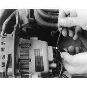
Connect an ammeter in series between the alternator's
Bterminal and the wire, then unplug the alternator's
multi-connector and attach jumper wires, as shown
Disconnect the wire from the Bterminal of the alternator, and
connect an ammeter between the Bterminal and the wire.
Refer to the accompanying illustration, as necessary, for
terminal designations.
Disconnect the alternator's multi-connector and attach jumper wires, as
shown.
Start the engine and run it at 2,000 rpm (you can use a dwell/tachometer
to measure rpm). Read the ammeter, and note the reading. Then, pull the wire
off the female Fterminal and connect it to the female Aterminal
just long enough to get a current reading. Shut off the engine.
If the amperage reading increases significantly, the trouble is in the
regulator; if it remains exactly the same, the trouble is in the alternator.
1980-82 626
With the ignition switch OFF, connect the voltmeter between the
Rterminal and ground, then read the voltage. Do the same for the
Lterminal. If there is voltage at either terminal, the alternator is
defective.
Connect the voltmeter and ammeter as shown to test
alternator output-1981-85 GLC and 1980-85 626 (except
diesel)
With the voltmeter still connected to the Lterminal, turn the
ignition switch ONand read the voltmeter. Note the reading, then check
the voltage across the battery terminals. Lterminal voltage should be
1-3 volts DC. If there is no voltage, the alternator or associated wiring is
bad. If the voltage is close to the battery's voltage, connect a jumper wire
between the Fterminal and ground. If the voltage at the
Lterminal drops lower than the battery voltage, this indicates that the
IC regulator may be faulty.
The F terminal is neither exposed on the surface of the
alternator rear bracket, nor marked for its location. It is located at a depth
of 0.79 in. (20mm) in a hole near the mark of B terminal.
WARNING
Do not start the engine with the connector for the L
and R terminals unplugged, and do not ground the L terminal while the
engine is running.
Start the engine and turn on the headlights. Gradually increase the engine
speed as you read the output voltage and current. If output voltage is higher
than battery voltage, and there is output current, the alternator is operating
satisfactorily.
On 1982 models, you can go a step further and check the no-load
adjustment voltage as follows:
With the battery fully charged, connect a voltmeter between the battery's
positive terminal and ground. Connect a voltmeter between the Lterminal
on the rear of the alternator and ground. Connect an ammeter between the
alternator's Bterminal and the battery's positive terminal. Jumper the
ammeter with a heavy-gauge wire (as illustrated by the dotted line) while
starting the engine, then remove the jumper. Run the engine at 2,000-2,500 rpm
(check rpm with a dwell/tach). This will turn the alternator 5,000 rpm. The
ammeter should read less than 5 amps, and the voltmeter 14.1-14.7 volts DC.
Now, turn on the lights. If the alternator responds by putting out increased
amperage, and the voltage is higher than the battery voltage, it is
functioning properly.
1981-85 GLC and 1983-85 626
EXCEPT DIESEL
With the ignition switch OFF, connect the voltmeter between the
Lterminal and ground, then read the voltage. If there is any voltage,
the alternator is defective.
With the voltmeter still connected to the Lterminal, turn the
ignition switch ONand read the voltmeter. If the reading is 0 volts,
there is probably a malfunction in the alternator, but check the wiring first.
If the voltage is close to the battery's voltage, connect a jumper wire
between the Fterminal and ground. If the voltage at the
Lterminal drops lower than the battery voltage, this indicates a
malfunction of the IC regulator.
WARNING
Do not start the engine with the connector for
the
L and Rterminals unplugged, and do not ground the Lterminal
while the engine is running.
Before checking the no-load adjustment voltage,
temporarily install a shunt (as indicated by the dotted line) to short
circuit the ammeter during engine start-up-1983-85 626
Start the engine and turn on the headlights. Gradually increase the engine
speed as you read the output voltage and current. If output voltage is higher
than battery voltage, and there is output current, the alternator is operating
satisfactorily.
Check the no-load adjustment voltage after installing a shunt to protect
the ammeter during start-up, as illustrated. With the battery fully charged,
connect a voltmeter between the battery's positive terminal and ground.
Connect a voltmeter between the Lterminal on the rear of the alternator
and ground. Connect an ammeter between the alternator's Bterminal and
the battery's positive terminal. Jumper the ammeter with a heavy-gauge wire
(as illustrated by the dotted line) while starting the engine, then remove the
jumper. Run the engine at 2,000-2,500 rpm (check rpm with a dwell/tach). This
will turn the alternator 5,000 rpm. The ammeter should read less than 5 amps,
and the voltmeter 14.4-15.0 volts DC (14.1-14.7 volts DC for the 1981-83 GLC).
Now, turn on the lights. If the alternator responds by putting out increased
amperage, and the voltage is higher than the battery voltage, it is
functioning properly.
1985 626 DIESEL
With the ignition switch OFF, connect the voltmeter between the
Lterminal and ground, then read the voltage. If there is voltage at the
terminal, the alternator is defective.
Turn the ignition switch ONand read the voltmeter. If the reading
is 0 volts, there is probably a malfunction in the alternator, but check the
wiring first. If the voltage is near the battery voltage, connect a jumper
wire between the Fterminal and ground. If the voltage at the
Lterminal drops lower than the battery voltage, this indicates a
malfunction of the IC regulator.
Alternator terminal connections-1985 626
diesel
Location of the F terminal on the 626 diesel
alternator
Connect the voltmeter and ammeter as shown to test
alternator output-1985 626 diesel
Disconnect the negative battery cable. Connect an ammeter and voltmeter,
as shown in the illustration. Then, reconnect the negative battery cable.
WARNING
Do not start the engine with the connector for
the
L and Rterminals unplugged, and do not ground the Lterminal
while the engine is running.
Start the engine and turn on the headlights. Gradually increase the engine
speed as you read the output voltage and current. If output voltage is higher
than battery voltage, and there is output current, the alternator is operating
satisfactorily.
1986-87 323 and 1986 626
Steps 1-8 should be followed if the battery constantly
discharges. If the battery overcharges, proceed to Step 9.
Start the engine and allow it to idle. Disconnect the alternator
Bterminal wire and connect an ammeter with a capacity of 60 amps or
more between the wire and the terminal.
CAUTION
Make connections carefully to avoid grounding the
Bterminal, which would burn out the alternator.
Turn headlights and all accessories on.
Speed the engine up until it is turning 2,500-3,000 rpm. Read the output
on the ammeter. Compare the reading with the nominal output shown on the
Alternator and Regulator Specifications chart. On the 323s, if the output is
90% or more of the nominal indicated output, the alternator is okay. On the
1986 626, a minimum output of 51 amps is normal. If the current reading meets
or exceeds the appropriate minimum level, turn off the headlights and
accessories, and shut off the engine, then remove the ammeter and reconnect
the alternator wire to terminal B. However, if the current reading does
not meet the applicable minimum level, proceed with the following steps.
Alternator terminal locations for the 1986
323
Alternator terminal locations for the 1986
626
Turn off all lights and electrical accessories. Charge the battery until
the charging rate is less than 5 amps at idle or replace the battery with one
that is fully charged, if available. Then, read the ammeter at 2,500 rpm. If
the reading is now more than 5 amps, there is a short (ground) somewhere in
the vehicle wiring. If the indication is still less than 5 amps, proceed with
the next step.
This step should be performed with the car at a normal room temperature of
about 68°F (20°C). Disconnect the ammeter and reconnect the alternator wire to
terminal B. Pull the R-Lconnector out just slightly, so you can
get the probe of a voltmeter in to read the voltage while the connection is
maintained. Connect a voltmeter to the Lterminal of the alternator and
to the alternator housing (ground). Accelerate the engine to 2,500 rpm and
read the voltage. If the reading is 14.4-15.0 volts DC, the problem is in the
alternator's stator coil and/or diodes. If it is less than 14.4 volts DC,
proceed with the next step.
Unplug the R-Lconnector from the alternator terminals. Connect a
voltmeter between the female Rterminal (coming from the wiring harness)
and the alternator housing or other ground. Then, turn the ignition switch
ONand measure the voltage. If it is equal to the battery's voltage,
proceed to the next step. If the measured voltage is lower, correct the
problem in the wiring harness.
Turn the ignition switch OFF. Disconnect the wire from the
Bterminal of the alternator. Measure the resistance between the
Land Fterminals with an ohmmeter. The resistance should be 3-6
ohms. If resistance is not within this range, the problem is in the field coil
(rotor) or slip ring, and the alternator must be replaced, or disassembled and
repaired. If resistance is 3-6 ohms, proceed with the following steps.
Reconnect the Bterminal connector to the alternator. Turn the
ignition switch ON. Pull the R-Lconnector out just slightly, so
you can get the probe of a voltmeter in to read the voltage while the
connection is maintained. Measure the voltage at the Lterminal prong.
If it is over 3.0 volts DC, the problem is in the regulator. If it is 1.0-3.0
volts DC, the problem is in the stator coil and/or diodes.
Perform the following steps only if the battery
overcharges:
Turn off all electrical loads. Run the test with the vehicle as close to
68°F (20°C) as possible. Disengage the wiring connector from the alternator's
Bterminal. Connect an ammeter with a minimum capacity of 60 amps
between the wire and the alternator's Bterminal. Start the engine and
run it to charge the battery until the charging rate is less than 5 amps. (If
you have a fully charged battery available, it will save time to install it in
place of the present one.) Pull the R-Lconnector out just slightly, so
you can get the probe of a voltmeter in to read the voltage while the
connection is maintained. Run the engine at 2,500 rpm and measure the voltage
at the Lterminal prong. If the voltage is 14.4-15.0 volts DC, the
alternator is okay. If it is over 15.0 volts DC, proceed with the next step.
Turn the engine OFF.
Disengage the Rconnector at the alternator. Connect a voltmeter
between the Rconnector and a good ground. Turn the ignition switch
ONand measure the voltage at the connector. If the voltage is less than
battery voltage, repair the wiring harness. If the voltage is equal to battery
voltage, proceed with the next step.
Turn the ignition switch OFF, then disconnect the wire from the
alternator's Bterminal. Connect an ohmmeter and measure the resistance
between the Land Fterminals. If resistance is 3-6 ohms, the
problem lies in the voltage regulator. If resistance is outside that range,
the problem is in the field coil or slip ring.
1987 626
Steps 1-10 should be followed if the battery constantly
discharges. If the battery overcharges, proceed to Step 11.
Disconnect the negative battery cable.
Disconnect the alternator Bterminal wire and connect an ammeter
with a capacity of 60 amps or more between the wire and the terminal.
CAUTION
Make connections carefully to avoid grounding the
Bterminal, which would burn out the alternator.
Reconnect the negative battery cable.
Turn the headlights and all accessories on, then depress (and hold) the
brake pedal.
Start the engine and idle it at 2,500-3,000 rpm. Read the output on the
ammeter; it should be a minimum of 55 amps. (If the current reading meets or
exceeds this level, the alternator is functioning normally. If the current
reading does not meet this level, proceed with the following steps.)
Turn off all lights and accessories, and release the brake pedal. Charge
the battery until the charging rate is less than 5 amps at idle or replace the
battery with one that is fully charged, if available. Then, read the ammeter
at 2,500 rpm. If the reading is now more than 5 amps, there is a short
(ground) somewhere in the vehicle wiring. If the indication is still less than
5 amps, proceed with the next step.
Alternator terminal connections-1987
626
This step should be done with the car at a normal room temperature of
about 68°F (20°C). Shut off the engine and disconnect the negative battery
cable. Disconnect the ammeter and reconnect the alternator wire to terminal
B. Reconnect the negative battery cable and restart the engine. Pull
the R-Lconnector out just slightly, so you can get the probe of a
voltmeter in to read the voltage while the connection is maintained. Connect a
voltmeter to the Lterminal of the alternator and to the alternator
housing (ground). Accelerate the engine to 2,500 rpm and read the voltage. If
the reading is less than 14.2 volts DC or more than 15.2 volts DC, there may
be a problem in the alternator's field coil or diodes. (However, such a
voltage reading could also stem from a poor connection between the
Bterminal and the positive battery cable, or from a poor connection of
the negative battery cable. It could also result from a poor connection
between the 2-pin R-Lconnector and the positive battery cable.) If the
voltage reading is 14.2-15.2 volts DC, proceed with the next step.
Turn the ignition switch OFFand unplug the R-Lconnector from
the alternator terminals. Connect a voltmeter between the female
Rterminal (coming from the wiring harness) and the alternator housing
or other ground. Then, turn the ignition switch ONand measure the
voltage. If it is equal to the battery's voltage, proceed to the next step. If
the measured voltage is lower, correct the problem in the wiring harness.
Turn the ignition switch OFF, then disconnect the negative battery
cable. Disconnect the wire from the Bterminal of the alternator, as
well as the R-Lconnector. Measure the resistance between the
Land Fterminals with an ohmmeter. The resistance should be 3-6
ohms. If resistance is not within this range, the problem is in the rotor coil
or brush(es), and the alternator must be replaced or disassembled and
repaired. If resistance is 3-6 ohms, proceed with the following steps.
Reconnect the wire to the alternator's Bterminal. Loosely attach
the R-Lconnector, so you can get the positive (+) probe of a voltmeter
in to read the voltage while the connection is maintained. Turn the ignition
switch ON. Connect the negative (-) probe of the voltmeter to the
alternator housing or other ground, and measure the voltage at the
Lterminal prong. If it is over 3.0 volts DC, the problem is in the
regulator. If it is 1.0-3.0 volts DC, the problem is in the stator coil and/or
diodes.
Perform the following steps only if the battery
overcharges:
Turn off all electrical loads. Perform this step with the vehicle as close
to 68°F (20°C) as possible. Disconnect the negative battery cable and the wire
from the alternator's Bterminal. Connect an ammeter with a minimum
capacity of 60 amps between the wire and the alternator's Bterminal.
Reconnect the negative battery cable. Start the engine and run it to charge
the battery until the charging rate is less than 5 amps. (If you have a fully
charged battery available, it will save time to install it in place of the
present one.) Pull the R-Lconnector out just slightly, so you can get
the probe of a voltmeter in to read the voltage while the connection is
maintained. Run the engine at 2,500 rpm and measure the voltage at the
Lterminal prong. If the voltage is 14.2-15.2 volts DC, the alternator
is okay. If it is over 15.2 volts DC, there is a problem in the alternator;
proceed with the next step.
Turn the ignition switch OFF. Disconnect the L-Rconnector at
the alternator. Connect a voltmeter between the female Rterminal
(coming from the wiring harness) and the alternator housing or other ground.
Turn the ignition switch ONand measure the voltage at the connector. If
the voltage is less than battery voltage, repair the wiring harness. If the
voltage is equal to battery voltage, proceed with the next step.
Turn the ignition switch OFF, then disconnect the negative battery
cable and the wire from the alternator's Bterminal. Connect an ohmmeter
and measure the resistance between the Land Fterminals on the
alternator. If resistance is 3-6 ohms, the problem lies in the voltage
regulator. If resistance is outside that range, the problem is in the rotor
coil or brush(es).
REMOVAL & INSTALLATION
Disconnect the battery ground cable at the negative (-) terminal.
Remove the air cleaner as required. Remove the nut, and disconnect the
alternator Bterminal. Unplug the connector from the rear of the
alternator.
Remove the nut, and disconnect the alternator
Bterminal
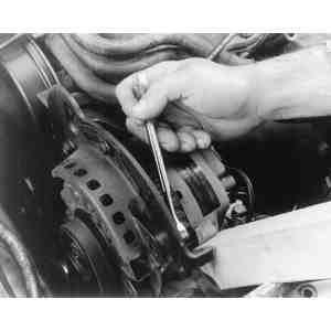
Remove the bolt which secures the alternator to the
adjusting link
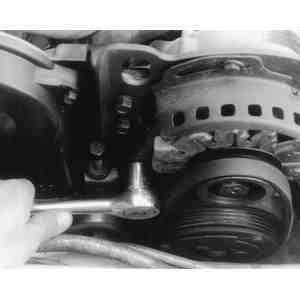
Loosen the alternator pivot bolt, and relax the drive
belt tension, before removing the drive belt(s)
Remove the alternator adjusting link bolt(s). Do not remove the adjusting
link. Remove the alternator drive belt. On the 626 diesel, this first requires
loosening the air conditioner idler pulley, then removing the two alternator
belts and the single air conditioning drive belt.
Remove the alternator securing nuts and bolts. Pull the drive belt(s) off
the pulley and remove the alternator.
To install:
Position the alternator onto its mounting and install the attaching
hardware.
Install the drive belt(s).
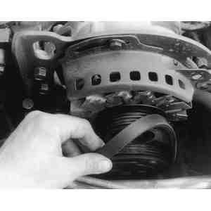
Remove the alternator drive belt(s) and then the
alternator
On 1979-82 RX-7s, alternator mounting clearance is
adjusted with shims
Plug the connector into the rear of the alternator. Clean the Bwire
terminal and install the wire with the nut.
Install the air cleaner, if removed, and connect the negative battery
cable.
Adjust the drive belt tension as described in Section 1.
On 1979-82 RX-7s, when installing the alternator, check the
clearance between the alternator and bracket. If the clearance is greater than
0.006 in. (0.15mm), reduce it with shims.
Regulator
All 1978-80 models, except the 626, are equipped with separate
voltage regulators that can be adjusted. While all 1981-89 models have IC
(integrated circuit) voltage regulators located inside the alternator housing.
These are not adjustable, and can only be replaced. All service on IC regulators
should be referred to a qualified technician.
REMOVAL & INSTALLATION
1978-79 GLC and RX-7
Disconnect the battery ground cable at the negative (-) battery terminal.
Disconnect the wiring from the regulator.
Remove the regulator mounting screws.
Remove the regulator.
To install:
Install the new regulator and attach with the mounting screws.
Connect the regulator wiring.
Connect the negative battery cable.
VOLTAGE ADJUSTMENTS
1978-79 GLC and RX-7
Remove the cover from the regulator.
Check the air gap, point gap and back gap with a feeler gauge (see
illustration).
If they do not fall within the specifications given in the Alternator and
Regulator Specifications chart, adjust the gap(s) by bending the stationary
contact bracket.
The air gap, point gap and back gap are adjustable on
1978-79 GLC and RX-7 voltage regulators
On the 1979 RX-7, connect a voltmeter between the
Aand Eterminals of the voltage regulator
Connect a voltmeter between the Aand Eterminals of the
regulator, on the RX-7. On the GLC, connect a voltmeter between the top
terminal of the alternator and the coil mounting bolt.
Be sure that the car's battery is fully charged before
proceeding with this test. The ammeter must read 5 amps or less.
Start the engine and run it at the rpm specified in the accompanying
chart. The voltage reading should as specified in the same chart.
Stop the engine.
Bend the upper plate down to decrease the voltage setting, or up to
increase the setting, as required.
If the regulator cannot be brought within specifications, replace it.
When the test is completed, disconnect the voltmeter and replace the
regulator cover.
Battery
REMOVAL & INSTALLATION
If so equipped, remove the protective battery shield.
Using the correct size wrench, loosen the nut which secures the negative
(-) cable clamp, then remove the negative (-) battery cable from its top
terminal post. If the battery has side terminals, simply loosen the retaining
bolt and disconnect the cable.
Using the correct size wrench, loosen the nut which secures the positive
(+) cable clamp, then remove the positive (+) battery cable from its top
terminal post. Again, if the battery has side terminals, simply loosen the
retaining bolt and disconnect the cable.
Remove the battery hold-down clamp or other hardware, then carefully
remove the battery from the vehicle.
To install:
Inspect the battery carrier and the fender panels for damage caused by
loss of battery acid.
If the battery is to be reinstalled, clean its top with a solution of
clean, warm water and baking soda. Scrub heavily deposited areas with a stiff,
bristly brush, being careful not to scatter corrosion residue.
Rinse off the top of the battery with clean, warm water.
Keep the cleaning solution and water out of the battery
cells.
Examine the battery case and cover for cracks.
Gently clean the battery posts and cable connectors (clamps) with a wire
brush. Replace damaged or worn cables.
Install the battery in the car. Tighten the hold-down clamp nuts or
associated hardware.
Connect the positive (+) cable to its corresponding battery terminal and
tighten the clamp nut or retaining bolt.
Connect the negative (-) cable to its corresponding battery terminal and
tighten the clamp nut or retaining bolt.
After securing the cables, coat the battery/cable connections with
petroleum jelly to prevent corrosion.
If the battery has filler caps and the electrolyte level is low, fill the
battery to the recommended level with distilled water.
If so equipped, install the protective battery shield.
There are two possible locations for the starter motor; one is the
lower right-hand side of the engine and the other is on the upper right-hand
side.
Remove the ground cable from the negative (-) battery terminal.
If the car is equipped with the lower mounted starter, remove the gravel
shield from underneath the engine. On vehicles equipped with automatic
transmission, remove the two bolts attaching the starter bracket to the
transmission. On 1989 323 with 4WD, remove the differential lock assembly from
the transaxle, as described in Section 7.
Common starter mounting-except RX-7 and 1988-89
626/MX-6
The solenoid is mounted on top of the
starter
Remove the battery cable from the starter terminal.
Label and disconnect the leads from the solenoid or magnetic switch
terminals.
Remove the starter securing bolts and withdraw the starter assembly.
To install:
Position the starter onto the flywheel housing and install the attaching
bolts. On 1986-89 323, 1986-87 626 and 1988-89 929, torque the starter
mounting bolts to 23-34 ft. lbs. (31-46 Nm).
Connect the leads to the appropriate terminals on the solenoid or magnetic
switch.
Connect the battery cable to the starter terminal.
On 1989 323 with 4WD, install the center differential lock assembly onto
the transaxle, as described in Section 7.
Install the starter bracket (automatic transmissions) or the gravel
shield, if removed.
Connect the negative battery cable.
1988-89 626/MX-6
Disconnect the negative battery cable.
Disconnect the starter wiring.
Raise the front of the vehicle and support it safely.
Starter mounting-1988-89
626/MX-6
Unbolt and remove the intake manifold bracket.
Remove the upper starter bolts and loosen, but do not yet remove the lower
bolt.
Remove the lower bolt and withdraw the starter from the lower side of the
vehicle.
To install:
Position the starter onto the flywheel housing and install the lower bolt
for support. Install the remaining bolts and torque all bolts to 27-38 ft.
lbs. (37-51 Nm).
Install the intake manifold bracket. Torque the bracket bolt to 27-38 ft.
lbs. (37-51 Nm) and the nut to 14-19 ft. lbs. (19-26 Nm).
Lower the vehicle.
Connect the starter wiring.
Connect the negative battery cable.
RX-7
The starter is mounted on the driver's side bottom of the
engine.
Disconnect the negative battery cable.
Raise the vehicle and support it safely with jackstands.
Starter mounting-1979-85 RX-7
Starter mounting-1986-89 RX-7
Disconnect the heavy battery cable from the terminal marked Bon the
starter solenoid (or magnetic switch on later models).
Disconnect the thinner ignition switch wire from the terminal marked
Son the solenoid/magnetic switch.
On vehicles with automatic transmissions, remove the front starter motor
bracket bolts and the bracket. Remove the two starter attaching bolts and
remove the starter.
To install:
Support the starter by and hand and position it onto the flywheel housing.
Install the two mounting bolts. On 1986-89 RX-7s, torque the bolts to 24-33
ft. lbs. (33-45 Nm). Install the front starter bracket, if removed.
Connect the starter wiring to the appropriate solenoid or switch
terminals. On 1986-89 models, torque the Bterminal (battery cable) nut
to 8 ft. lbs. (11 Nm).
Lower the vehicle.
Connect the negative battery cable.
SOLENOID REPLACEMENT
Perform solenoid replacement with the starter motor removed
from the car. On later model starters, the solenoid is referred to as a magnetic
switch; these terms are interchangeable.
Disconnect the negative battery cable.
CAUTION
This is necessary as the wiring coming from the
battery could ground and cause a fire or other
damage!
Detach the field strap, the "hot wire" from the battery, and the ignition
wiring connector from the solenoid terminals.
Remove the solenoid securing bolts.
Magnetic switch (solenoid)
mounting
To check pinion gap, energize the solenoid with jumper
wires ...
... and insert a feeler gauge between the front of the
pinion gear and the starter body
Withdraw the solenoid, washers, spring and plunger, lifting the assembly
to disconnect the plunger where it engages with the fork.
Assemble the plunger, spring, washers and solenoid assembly and engage the
plunger with the fork.
Hold the plunger assembly in place and install the attaching screws.
Reconnect the starter-to-solenoid wiring.
Assemble the solenoid, then check the pinion gap as follows:
Leave the connection between solenoid terminal Mand the starter
motor disconnected.
Energize the solenoid by running one jumper wire from the battery's
positive (+) terminal to the Sterminal connection of the solenoid,
and another jumper wire from the negative (-) battery terminal to the body
of the solenoid.
The solenoid will engage without spinning the starter.
Measure the pinion gap with a feeler gauge, as shown. If it is not
0.020-0.079 in. (0.5-2.0mm), correct it by changing the number of washers
(increase the number of washers to reduce the gap).
WARNING
The solenoid should not be energized for more than 20
seconds at a time, or it will overheat.
OVERHAUL
On cars with automatic transmissions, remove the bracket from the rear of
the starter.
Disconnect the field strap from the terminal on the solenoid, remove the
solenoid attaching screws, and remove the solenoid, spring and washers.
Detach the plunger at the drive lever, and remove it.
Remove the starter through-bolts and the brush holder attaching screws.
Matchmark the rear bracket/cover with the yoke housing. Remove the rear cover.
Remove the insulator and washers from the rear end of the armature shaft.
Remove the brush holder and the wave washer (later models).
Matchmark the yoke and front housing. Pull the yoke off the drive housing.
Remove the rubber packing, spring and spring seat.
Pull the armature, drive lever and overrunning clutch assembly from the
drive housing. Note the direction of the drive lever before removing it. Do
not lose the ball (later models).
Position the armature with the front end upward in a soft jawed vise.
Drive the pinion stop collar rearward until the stop ring can be removed.
Then, remove the stop ring, stop collar and overrunning clutch.
Disconnect the brush from the brush holder using a suitable prying tool,
and remove it from the rear housing.
Starter components-representative of 1987-89
models
Yoke and armature mounting
Removing the overrunning clutch
stopper
Disconnecting the brush from the brush
holder
Inspect all internal and planetary gears for wear or damage. Replace as
necessary.
Grasp the overrunning clutch and turn the pinion shaft. If the pinion
shaft turns in both directions, or does not turn at all, replace it.
The clutch assembly is packed with grease. Do not attempt to
wash the overrunning clutch with solvent or any other type of cleaning
agent.
Check the commutator shaft bearing for any abnormality such as noise, wear
or binding. If the bearing is bad, remove it with a suitable bearing puller
and install a new bearing.
Check the yoke for damage and replace it as necessary.
To assemble the starter:
Lubricate the following components with grease prior to assembly:
Armature shaft gear
Internal and planetary gears
Plunger circumference
Lever
Ball (later models)
Gear shaft spline
Front bracket bushing
Connect the brush to the brush holder in the rear housing.
Slide the overrunning clutch, stopper and snapring onto the armature
shaft, then position the assembly on a press. Press the stopper onto the shaft
and secure it with the snapring.
Insert the armature, drive lever and clutch assembly into the drive
housing. Make sure the lever is facing in the original direction.
Assemble the armature and the yoke by aligning the matchmarks and install
the assembly onto the front housing.
Install the brush holder assembly and washer into the rear housing.
Install the through-bolts making sure that they are properly aligned with the
brush holder. Install and tighten the brush holder retaining screws.
Install the solenoid as described above. Energize the solenoid by
connecting the Sterminal on the solenoid to the battery's positive (+)
terminal, and grounding the solenoid housing to the battery's negative (-)
terminal. Check the clearance between pinion and stop collar with a feeler
gauge. It should be 0.020-0.079 in. (0.5-2.0mm). If the clearance is
incorrect, install adjusting washers, which are available for insertion
between the solenoid and drive housing.
STARTER BRUSH REPLACEMENT
The four brushes are arranged around the commutator of the starter
at right angles to each other. Inspect the brushes for excessive wear. The wear
limit for all vehicles except 1987-89 RX-7s is 0.453 in. (11.5mm). On 1987-89
RX-7s, the wear limit is 0.394 in. (10mm).
If worn beyond the limit, they must be replaced. Another way of
checking brush length is to locate the little three diamond insignia on the side
of the brush; if the brush is worn down to this insignia, it must be replaced.
Remove the brush from the holder. Smash the brush in order to free the
lead from it. Clean old solder and corrosion from the lead.
Measuring the brush wear
limit
Soldering brush leads to the
brushes
Insert the lead into the new brush, using the end with the smaller
chamfer.
Solder the lead into the brush by filling the large chamfer with rosin
core solder. A small soldering iron rated at about 150 watts is best. Smooth
the outer surface of the soldered connection with sandpaper after the
soldering is complete.
Install the brush in the brush holder under the spring. When fitting the
brush plate with the brushes in it over the commutator, use a small
screwdriver to push the brushes back a little.