Most transaxle codes are available from the vehicle information
code plate located on the cowl (in the engine compartment). The first portion of
the code is the transmission designation; following this, there is a blank box.
At the right end of the line is the axle or final drive ratio.
On other models the transaxle model and serial number are either
stamped on a plate that is bolted to the transmission case or stamped directly
on the case itself. The location varies from model-to-model.
Adjustments
SHIFT LEVER ADJUSTMENT
Front Wheel Drive
The shift lever on most models may be adjusted during transmission
installation by means of adjusting shims on the three bolts between the cover
plate and the packing. The force required to move the shift knob should be
4.4-8.8 lbs. (2-4 kg).
Four Wheel Drive
Set the transaxle shift lever (in the vehicle) to the Neutral position.
On the transaxle, make sure the shift and select levers are also in the
Neutral position.
Remove the shift lever console.
Disconnect the shift and select cables from the control levers by removing
the pins, flat washers and spring clips. The clips must be replaced.
Make sure the select cable end hole aligns with the select lever pin. If
not aligned, loosen cable adjusting nut Aand rotate the cable end until
the holes are aligned.
Place the shift lever at the center of its front-to-rear stoke.
Make sure the select cable end hole aligns with the select lever pin. If
not aligned, loosen cable adjusting nut Band rotate the cable end until
the holes are aligned.
Connect the cables.
Shift lever adjustment-1988-89 323 with
4wd
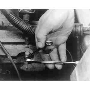
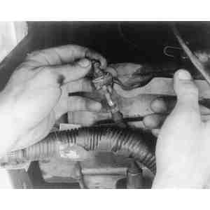
Back-Up Light Switch
REMOVAL & INSTALLATION
The back-up light switch is threaded into the transaxle case.
Disconnect the negative battery cable.
Remove the wire clamp from the transaxle case that secures the switch
wire.
Disengage the electrical wiring multi-connector.
Loosen and remove the switch from the transaxle case.
To install:
Remove the metal gasket from the switch and install a new one.
Thread the switch into the transaxle case and tighten just enough to crush
the gasket.
Connect the wiring and install the wire clamp.
Connect the negative battery cable and check for proper switch operation.
Transaxle
REMOVAL & INSTALLATION
GLC
Raise the vehicle and support it safely. Disconnect the negative battery
cable.
Disengage all electrical wiring and connections. Mark these units to aid
in reassembling. Drain the transaxle oil.
Remove the front wheels. Disconnect the lower ball joints from the
steering knuckles. Pull the driveshafts from the differential gears.
A circlip is positioned on the driveshaft ends and engages in a
groove, machined in the differential side gears. The driveshafts may have to be
forced from the differential housing to release the clip from the groove. Do not
apply a sharp impact. Do not allow the driveshaft's free end to drop, otherwise
may occur to the ball and socket joints as well as to the rubber boots. Wire the
shafts to the vehicle body when released from the differential.
Support the engine with a jack or lift, and raise it slightly. Now,
separate the shift control rod from the shift rod.
Remove the extension bar from the transaxle. Remove the crossmember.
Remove the rubber mount from the transaxle case. Remove the starter.
Support the transaxle securely with a jack. Then remove the transaxle
mounting bolts, and remove it from the car.
To install:
Raise the transaxle into position with the jack, then install and tighten
the mounting bolts.
Install the starter and connect the wiring. Install the rubber mount onto
the transaxle case.
Bolt the crossmember to the frame and connect the extension bar to the
transaxle.
Connect the shift rod to the control rod.
Insert the driveshafts into the differential gears. Connect the lower ball
joints to the steering knuckles. Mount the front wheels.
Connect all electrical wiring and the negative battery cable.
Fill the transaxle to the proper level and adjust the clutch linkage.
Exploded view of GLC's manual
transaxle
Disconnecting shift linkage and removing the
crossmember-GLC manual transaxle
Observe the indicated torque values when
assembling/installing the transaxle
1983-87 626
Disconnect the negative battery cable.
Disconnect the speedometer cable at the transaxle.
Remove the clutch cable bracket mounting bolts. Disconnect the cable at
the release lever, then remove the mounting bracket.
Loosen the nuts which secure the clutch cable to the
release lever ...
... then disengage the cable from the
lever
Remove the ground wire attaching bolt and the wiring harness clip from the
transaxle. Remove the starter.
Support the engine via the hooks in a secure manner from above.
Remove the four bolts which couple the engine to the transaxle.
Jack up the vehicle and support it securely. Drain the transaxle oil.
Remove the front wheels and the splash shields. Remove the stabilizer bar
control link.
Remove the protective cover, if so equipped. Remove its coupling bolt,
then separate the lower control arm ball joint from the steering knuckle by
pulling downward on the lower control arm. Be careful not to damage the ball
joint dust cover.
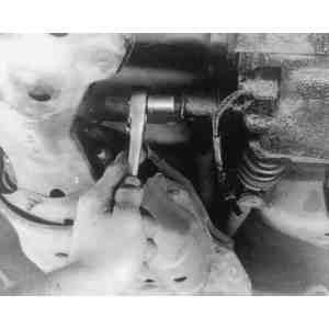
Insert a lever between the left-side driveshaft U-joint and the transaxle
as shown, then gently tap the end of the lever to pull the driveshaft out of
the differential side gear. Be careful not to damage the oil seal in the case.
Pull outward on the brake rotor and caliper while holding the inner end of the
shaft to guide it straight out of the transaxle case. This will prevent damage
to the oil seal.
Removing the left-side driveshaft from the 626
transaxle
Removing the right-side driveshaft from the 626
transaxle
Insert a lever between the right-side driveshaft and joint shaft
(cross-shaft), as shown, then gently tap the lever to uncouple the two. Pull
forward on the brake caliper/rotor assembly on this side and separate the two
shafts. Now, remove the cross-shaft bracket mounting bolts and remove the
shaft/bracket assembly from the transaxle.
Remove the nuts from the transaxle mounting bracket where it connects with
the crossmember. Then, remove the crossmember and the left lower arm as an
assembly.
Disconnect the shift control rod from the shift rod. Disconnect the
locating rod (extension bar) at the transaxle. Remove the protective cover
from under the transaxle.
Disconnect the locating rod at the
transaxle
Using a lift and chains or heavy rope, support the transaxle mounting
bracket at two places and at the engine support. Support at three locations is
necessary because the unit is not balanced. Remove the two bolts fastening the
transaxle and engine together, then separate the transaxle from the engine.
You can lower the unit from the car with a jack located underneath, but make
sure the chains or rope are kept under some tension to stop the unit from
tipping. Remove the mount brackets from the unit.
To install:
Installation of the transaxle is essentially the reverse of the removal
procedure. Please note the following:
Coat the spline of the primary shaft gear with molybdenum disulfide
grease prior to assembling the transaxle to the engine.
Make sure to steady the transaxle with chains or ropes while installing
it.
Replace the clips at the inner ends of the driveshaft and cross-shaft back
into the transaxle, but first turn the differential side gear by inserting
your finger into the shaft hole so the shaft splines and gear recesses will
fit into one another. Force the shaft in so the spring clip will lock. After
the shaft is installed, connect it to the driveshaft. Then, pull the front
disc-caliper assembly outward to make sure the driveshaft will not come out of
the transaxle.
When installing the other driveshaft, use the same general technique to
first force the spring clip to lock and then check that it has locked in a
similar manner.
Observe the following torque figures:
Transaxle mount-to-transaxle: 28-38 ft. lbs. (38-51 Nm)
Transaxle-to-engine bolts: 66-85 ft. lbs. (89-115 Nm)
Cross-shaft bracket mounting bolts: 32-45 ft. lbs. (43-61 Nm)
Ball joint-to-steering knuckle: 32-40 ft. lbs. (43-54 Nm)-When torquing
the nuts fastening the stabilizer bar to the control link, make sure that 1
in. (25mm) of bare thread is visible.
Engine-to-transaxle bolts: 66-68 ft. lbs. (89-92 Nm)
Engine mount installing nuts: 17-21 ft. lbs. (23-28 Nm)
1988-89 626 and MX-6
Remove the battery and battery carrier.
Disconnect the main fuse block, distributor lead and air flow meter
connector. Remove the air cleaner assembly.
On turbocharged engines, disconnect the intercooler hoses. On
non-turbocharged engines, remove the resonance chamber.
Disconnect the speedometer cable and the transaxle grounds.
Raise and support the vehicle safely, then remove the front wheels and
splash shield. Drain the transaxle oil into a suitable waste container.
Remove the clutch release cylinder and disconnect the tie rod ends using
the proper tool.
Remove the stabilizer control links. Remove the nuts and bolts from the
lower control arm ball joints, then pull the lower control arms downward to
separate them from the steering knuckles. Be careful not to damage the ball
joint dust boots.
Insert a small pry bar between the left driveshaft and the transaxle case,
then tap the end of the lever to uncouple the driveshaft from the differential
side gear. Pull the front hub forward and separate the driveshaft from the
transaxle. Remove the left joint shaft bracket. Separate the right driveshaft
and joint shaft in the same manner as the left.
Do not insert the lever too deeply between the shaft and the
case or the oil seal lip could be damaged. To avoid damage to the oil seal, hold
the CV-joint at the differential with one hand and pull the driveshaft straight
out.
Once both drive and joint shafts are removed, install differential side
gear holders 49-G030-455 (turbo), 49-G027-003 or their equivalents in the
differential side gears to hold them in place and prevent misalignment.
Remove the gusset plates and under cover. Remove the extension bar and the
control rod. Remove the surge tank bracket. Disconnect the wiring and remove
the starter.
Suspend the engine from the engine hanger bracket with a suitable lifting
device or engine support fixture.
No. 4 transaxle mount-1988-89 626 and
MX-6
No. 2 transaxle mount-1988-89 626 and
MX-6
Remove the No. 4 and No. 2 engine mounts and bracket. Disconnect the
rubber hanger from the crossmember, then remove the crossmember and left-side
lower control arm as an assembly.
Lean the engine towards the transaxle and support the transaxle with a
jack. Remove the transaxle-to-engine mounting bolts and slide the transaxle
from underneath the vehicle.
To install:
Attach a thick rope to two places on the transaxle. Place a board on the
jack and lower the transaxle onto the board. Using the jack, lift the
transaxle into position and throw the end of the rope over the support fixture
bar. Tension the rope to guide the transaxle onto its mounts while lifting the
transaxle with the jack. Once the transaxle is in place, have an assistant
install the transaxle-to-engine mounting bolts and torque them to 66-68 ft.
lbs. (89-92 Nm). Install the No. 4 engine mount and torque nuts Ato
47-66 ft. lbs. (64-89) and nuts Bto 49-69 ft. lbs. (66-93 Nm). Install
the No. 2 engine mount and torque nuts Aon non-turbo engines to 27-38
ft. lbs. (37-51 Nm) and 49-69 ft. lbs. (66-93 Nm) on turbo engines. Torque
nuts Bto 55-69 ft. lbs. (75-93 Nm) on both engines.
Install the crossmember and left-side lower control arm assembly. Torque
the bolts to 27-40 ft. lbs. (37-51 Nm) and the nuts to 55-69 ft. lbs. (75-93
Nm).
Remove the jack and rope. Remove the support fixture.
Install the starter and connect the wiring. Attach the surge tank bracket
and gusset plate. Install the end plate, clutch release cylinder and remaining
gusset plates. Torque the gusset plate bolts to 27-38 ft. lbs. (37-51 Nm).
Replace the clips at the inner ends of the driveshaft and cross-shaft back
into the transaxle, but first turn the differential side gear by inserting
your finger into the shaft hole so the shaft splines and gear recesses will
fit into one another. Force the shaft in so the spring clip will lock. After
the shaft is installed, connect it to the driveshaft. Then, pull the front
disc-caliper assembly outward to make sure the driveshaft will not come out of
the transmission. When installing the other driveshaft, use the same general
technique to first force the spring clip to lock and then check that it has
locked in a similar manner.
Connect the lower arm ball joints to the steering knuckles and torque the
nuts to 32-40 ft. lbs. (43-54 Nm). Clean the inside of the under cover and
fill the notches with a suitable silicone sealant. Install the under cover and
torque the retaining bolts to 67-95 inch lbs. (8-11 Nm).
Install the stabilizer bar control link and thread the nuts so that 0.79
in. (20mm) of the through-bolt protrudes above the bar. Once this dimension is
obtained, hold the adjusting nuts and torque the locknuts to 12-17 ft. lbs.
(16-23 Nm). Connect the tie rod ends using new cotter pins. Torque the tie rod
end nuts to 22-33 ft. lbs. (30-45 Nm).
Install the splash shields, front wheels, transaxle ground wire,
speedometer cable, intercooler hoses and air cleaner assembly (w/air flow
meter connector). Connect the distributor lead, then install the main fuse
block, battery and battery carrier. Fill the transaxle to the proper level.
323 Models
2WD
Disconnect the negative battery cable. Remove the air cleaner. Loosen the
front wheel lug nuts.
Disconnect the speedometer from the transaxle. Disconnect the clutch cable
from the release lever and remove the clutch cable bracket mounting bolts.
Remove the ground wire installation boot. Remove the water pipe bracket.
Remove the secondary air pipe and the EGR pipe bracket.
Remove the wire harness clip. Disconnect the coupler for the neutral
switch and back-up lamp switch. Disconnect the body ground connector.
Remove the two upper transaxle mounting bolts. Mount the engine support
tool 49-ER301-025A or equivalent to the engine hanger.
Raise and support the vehicle safely. Drain the transaxle oil into a
suitable container and remove the front wheels.
Remove the engine under cover and side covers. Remove the front
stabilizer.
Remove the lower arm ball joints and the knuckle clinch bolts, then pull
the lower arm downward and separate the lower arms from the knuckles.
Separate the driveshaft by pulling the front hub outward. Make sure not to
use too much force at once, increase the force gradually. Be sure the
driveshaft's ball joint is bent to its maximum extent. Do not allow the axle
shafts to drop, otherwise damage may occur to the ball and socket joints as
well as to the rubber boots. Wire the shafts to the vehicle body when released
from the differential.
Crossmember mounting and brackets-323 with
2wd
Remove the transaxle crossmember. Separate the change control rod from the
transaxle. Remove the extension bar from the transaxle. Remove the wiring and
the starter motor.
Remove the end plates. Lean the engine toward the transaxle side to lower
the transaxle by loosening the engine support hook bolt. Support the transaxle
with a suitable transaxle jack.
Remove the necessary engine brackets. Remove the remaining transaxle
mounting bolt and No. 2 engine bracket. Lower the jack and slide the transaxle
out from under the vehicle.
To install:
Before installing the transaxle, coat the splines of the primary shaft
gear with molybdenum disulfide grease.
Attach a thick rope to two places on the transaxle. Place a board on the
jack and lower the transaxle onto the board. Using the jack, lift the
transaxle into position and throw the end of the rope over the support fixture
bar. Tension the rope to guide the transaxle onto its mounts while lifting the
transaxle with the jack. Once the transaxle is in place, have an assistant
install all the transaxle-to-engine mounting bolts. Torque the bolts to to
47-66 ft. lbs. (64-89 Nm).
Install the end plates and the starter motor. Install the extension bar
and control rod. Torque the extension bar nuts to 23-34 ft. lbs. (31-46 Nm)
and the change control rod nuts to 12-17 ft. lbs. (16-23 Nm).
Attach the No. 2 mounting bracket to the transaxle and torque the bracket
bolts to 27-38 ft. lbs. (37-51 Nm). Install the crossmember and left-side
lower control arm assembly. Torque bolts Ato 47-66 ft. lbs. (64-89 Nm)
and bolts Bto 20-34 ft. lbs. (27-46 Nm).
Remove the jack and rope. Remove the support fixture.
Install the starter and connect the wiring. Attach the surge tank bracket
and gusset plate. Install the end plate, clutch release cylinder and remaining
gusset plates. Torque the gusset plate bolts to 27-38 ft. lbs. (37-51 Nm).
Replace the clips at the inner ends of the driveshaft and cross-shaft back
into the transaxle, but first turn the differential side gear by inserting
your finger into the shaft hole so the shaft splines and gear recesses will
fit into one another. Force the shaft in so the spring clip will lock. After
the shaft is installed, connect it to the driveshaft. Then, pull the front
disc-caliper assembly outward to make sure the driveshaft will not come out of
the transmission. When installing the other driveshaft, use the same general
technique to first force the spring clip to lock and then check that it has
locked in a similar manner.
Connect the lower arm ball joints to the steering knuckles and torque the
nuts to 32-40 ft. lbs. (43-54 Nm).
323 stabilizer bar adjustment
Install the stabilizer bar and adjust as follows: Tighten the locknuts and
the adjusting nuts so that 0.43 in. (11mm) of the through-bolt threads
protrude above the top of nut Bin the illustration. This is dimension
C. Once this dimension is obtained, tighten nut Bto 23-33 ft.
lbs. (31-45 Nm) and bolts Ato 9-13 ft. lbs. (12-18 Nm). Connect the tie
rod ends using new cotter pins.
Install the engine under and side covers. Install the front wheels and
lower the vehicle. Connect the body ground wire, then engage the neutral and
back-up switch coupler. Install the EGR pipe bracket, secondary air pipe and
water pipe bracket. Attach the clutch cable mounting bracket and connect the
clutch cable to the release lever.
Connect the speedometer cable, then install the air cleaner assembly.
Connect the negative battery cable. Adjust clutch and shift linkage as
required. Refill the transaxle with the proper grade of gear oil.
4WD
Remove the battery and the air cleaner assembly. Disconnect the
speedometer cable in the center. Remove the clutch release cylinder retaining
bolt and clip, then remove the clutch release cylinder. Raise and support the
vehicle safely, then drain the transaxle andengine oil.
Disconnect the neutral safety switch, back-up lamp switch, differential
lock sensor switch and differential lock motor electrical connectors.
Disconnect the transaxle shift and select control cables from the transaxle by
removing the pins and cable retaining clips. Route the cables off to the side
and out of the way.
Mount the engine support fixture 49-8017-5A0 or equivalent to the engine
strut mounting blocks. To mount the support fixture, first the nuts must be
removed from the mounting blocks. Remove the No. 4 engine mount bracket and
remove the front wheels.
No. 4 mounting bracket-323 with
4wd
Remove the side cover and under cover. Remove the driveshaft and
crossmember. Remove the oil filter and differential lock assembly (the
differential lock assembly is fastened with three bolts). Disconnect the
starter wiring, then remove the starter and stabilizer bar.
Disconnect the tie rod end from the lower control arm. Insert a small pry
bar between the driveshaft and the transaxle case, then tap the end of the
lever to uncouple the driveshaft from the differential side gear. Remove the
remaining driveshaft in the same manner. Insert differential side gear holder
49-B027-001 or equivalent to hold the side gears in place and prevent
misalignment.
Remove the end plate bolts, then connect a suitable hoist and lifting
strap to the transaxle. Lift the transaxle and transfer carrier assembly out
of the engine.
To install:
Attach a thick rope to two places on the transaxle. Place a board on the
jack and lower the transaxle onto the board. Using the jack, lift the
transaxle into position and throw the end of the rope over the support fixture
bar. Tension the rope to guide the transaxle onto its mounts while lifting the
transaxle with the jack. Once the transaxle is in place, have an assistant
install all the transaxle-to-engine and transfer mounting bolts. Torque the
bolts to 66-86 ft. lbs. (89-117 Nm).
Install the end plates.
Replace the clips at the inner ends of the driveshaft and cross-shaft back
into the transaxle, but first turn the differential side gear by inserting
your finger into the shaft hole so the shaft splines and gear recesses will
fit into one another. Force the shaft in so the spring clip will lock. After
the shaft is installed, connect it to the driveshaft. Then, pull the front
disc-caliper assembly outward to make sure the driveshaft will not come out of
the transmission. When installing the other driveshaft, use the same general
technique to first force the spring clip to lock and then check that it has
locked in a similar manner. When installing the joint shaft, torque mounting
bolts to 31-46 ft. lbs. (42-62 Nm).
Connect the tie rods to the lower arm and torque the pinch bolts to 32-40
ft. lbs. (43-54 Nm). Install and adjust the stabilizer bar as described in
Step 21 of the 2wd 323's procedure. Dimension Cfor 4wd vehicles is 0.33
in. (8.5mm) and the torque specs are the same.
Install the starter, differential lock assembly, oil filter, driveshaft,
side covers and under covers. Install the front wheels and lower the vehicle.
Install the No. 4 mounting bracket. Torque nuts Ato 37-45 ft. lbs.
(50-61 Nm) and nuts Bto 14-19 ft. lbs. (19-26 Nm).
Remove the support fixture and replace the strut mounting block nuts.
Torque the nuts to 17-22 ft. lbs. (23-30 Nm). Connect the shift and select
control cables using new retaining clips. Connect all the electrical and
sensor wiring.
Fill the transaxle to the proper level through the speedometer drive gear
opening. Fill the crankcase. Adjust the shift and select control cables as
previously described.
OVERHAUL
Disassembly and Assembly of Major Components
The following procedures cover both the 4-speed and 5-speed
transaxles on all applicable models. The 5-speed unit has a rear cover which
easily distinguishes it from the other unit.
5th GEAR
Remove the rear cover. Remove the roll pin that secures the 5th gear shift
fork to the selector shaft. Shift the transaxle unit into either 1st or 2nd
gear.
Do not shift into 4th gear or you may cause damage to the
gears.
Move the 5th gear clutch sleeve, to engage 5th gear and double lock the
transaxle.
Straighten the tab of the locknut on both the primary and secondary
shafts. Remove the locknuts from the shafts.
Pull the 5th gear clutch hub assembly out along with the 5th fork.
Remove the fork to gain access to the primary shaft
locknut.
Reinstall the 5th gear clutch hub and move the sleeve to the 5th gear
position in order to lock the transaxle.
Remove the primary shaft locknut and remove the 5th gear from the
transaxle case.
To assemble:
Install the 5th gear on the primary shaft. Be sure that the marked boss is
facing toward the locknut. Install the bushing and the 5th gear on the
secondary shaft.
Install the synchronizer ring, the clutch hub and the selector fork. Do
not install the shift fork pin.
The stop washer or plate for the clutch hub must be installed
between the locknut and clutch hub to prevent overtravel of the clutch when
shifting into reverse gear and to prevent the synchronizer keys from falling
out.
Install the locknuts on both shafts and tighten them slightly.
Shift into 1st or 2nd gear only, using the control rod. Shift into 5th
gear to double lock the transaxle.
Tighten the primary shaft locknut and lock the hub.
Do not tighten the secondary shaft locknut until the selector
fork is installed. Remove the locknut and clutch hub from the secondary gear
shaft, then reassemble it with the selector fork. Do not insert the drive pin at
this time.
Move the 5th gear selector clutch to engage the 5th gear in order to lock
the transaxle.
Shift the unit into either 1st or 2nd gear.
Install the roll pin securing the 5th gear shift fork to the selector
shaft. Install the cover.
PRIMARY SHAFT
The Mazda manual transaxle uses two types of primary shafts, one
for the 4-speed transaxle and another for the 5-speed transaxle. Both shafts are
made as a cluster with reverse, 1st, 2nd, 3rd and 4th gears integral. The 5th
gear (when equipped) is splined into the end of the shaft.
SECONDARY SHAFT
The secondary shaft assembly consists of the secondary shaft,
gears, clutch hub and sleeve assemblies, synchronizer rings and bearings. The
secondary shaft is manufactured integrally with the final drive gear.
There are three different types of secondary shafts used in the
4-speed transaxle and 2 different types used in the 5-speed transaxle. All of
these shafts vary by the number of gear teeth on the final drive gears.
The combination of the final drive gear on the secondary shaft
and ring gear are identified by the groove provided in the construction of each
individual gear.
SECONDARY GEARS
Install a suitable bearing puller in the grooves between the gear and the
gear spline of 4th gear. Remove the bearing and the 4th gear from the
assembly.
Remove the snapring on the 3rd and 4th clutch hub. Slide out the clutch
hub and the sleeve assembly.
Remove the 3rd gear, the thrust washer and the 2nd gear.
Remove the snapring, then slide out the clutch hub and reverse gear
assembly and 1st gear.
Install the bearing remover tool under the rollers and press out the
shaft.
Assembly is the reverse of disassembly.
SYNCHRONIZER RINGS
Bridge-type synchronizer rings are used in the Mazda transaxle.
There are three different synchronizer rings; 1 for 2nd, 3rd and 4th speed,
another for 1st and 3rd speed and 1 for 5th speed, if the vehicle is so
equipped. The 1st speed synchronizer ring can be identified from the other two
because it has fewer teeth.
THRUST CLEARANCE
The thrust clearance of each gear is checked by using a feeler
gauge. The specification for thrust clearance is 0.02 in. (0.5mm).
REVERSE IDLER SHAFT AND SHIFT ROD
The reverse idler shaft has an integral mounting post which is
secured to the case with a bolt. When installing the idler shaft, align the
holes of the shaft with the notch in the transaxle case. When installing reverse
shift rod to the shift gate, be sure that the screw holes are aligned and that
the hole of the shift rod is not 180 degrees out of phase.
Reverse idler shaft alignment
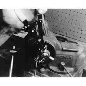
BEARING PRELOAD ADJUSTMENT
When the clutch housing, transaxle case, primary shaft,
secondary shaft, bearings or differential case are replaced, the bearing preload
should be checked and adjusted as necessary.
Remove the oil seal and the differential bearing outer race. Adjust the
shim from the transaxle case.
Remove the bearing outer races from the primary and secondary shafts.
Adjust the shims from the transaxle case and the clutch housing.
Reinstall the outer races to the transaxle case.
Install the outer races (removed in Step 2) to their respective selectors.
Install the selectors, primary shaft assembly and secondary shaft assembly to
the clutch housing.
Install the transaxle case, then place the ten collars between the
transaxle case and the clutch housing.
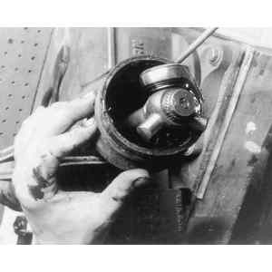
Collar positioning
To properly settle each bearing, using the tool, turn the selector in a
direction where the gap is widened until it cannot be turned by hand. Then
turn the selector in the opposite direction until the gap is eliminated.
Manually turn the selector to a direction where the gap becomes wider until
the selector cannot be turned.
Make sure that the shaft turns smoothly.
Measure the gap of the selector with a feeler gauge.
This measurement should be taken at 90 degree intervals along
the circumference of the selector.
Take the maximum reading and determine the shim to be used as follows.
For the primary shaft bearing, first subtract 0.04 in./1mm (thickness of
the diaphragm spring) from the gap (determined in Step 7).
Example: Gap measurement of 0.054 in. (1.39mm) minus 0.039 in.
(1mm) equals 0.015 in. (0.39mm); select the next larger and closer shim, which
would be 0.016 in. (0.40mm).
Do not use more than 2 shims.
For the secondary shaft bearing, select a shim which has a thickness that
is larger and closer to the gap (determined in Step 7).
Example: For a gap measurement 0.017 in. (0.42mm), select the next
larger and closer shim, which would be 0.018 in. (0.45mm).
Do not use more than 2 shims to accomplish this task.
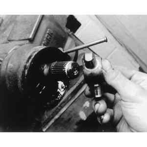
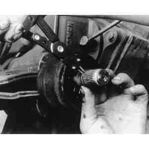
For the differential bearing, set the preload adapters (tool 49-00180-510A
and 49-FT01-515 or equivalents) to the pinion shaft through the hole for the
driveshaft of the transaxle case. Hook a spring scale to the adapter and check
the bearing preload.
Checking differential bearing
preload
While checking the preload, turn the selector until the reading
of the spring scale becomes 1.1-1.5 lbs. (0.50-0.68 kg).
Measure the gap of the selector on the differential using a feeler gauge.
This measurement should be taken at 90 degree intervals along
the circumference of the selector.
Select a shim that has a thickness larger and closer to the maximum
reading that was taken in the previous step.
Example: For a gap measurement of 0.021 in. (0.54mm), select the
next larger and closer shim, which would be 0.024 in. (0.60mm).
Do not use more than 3 shims to accomplish this task.
Remove the shim selectors and each bearing outer race. Install the shims
selected in previous steps between the transaxle case and bearing outer race.
Selected shim installation
locations
A diaphragm spring is used to keep the bearing preload as
specified and also to maintain low level gear noise. When installing the
diaphragm spring, be sure it is in the proper direction.
When installing the oil funnel on the clutch housing, be sure that it is
in the proper position.
After transaxle assembly, recheck the preloads of the differential bearing
and the primary shaft bearing.
The differential bearing preload should be 0.3-6.6 inch lbs. 0.034-0.739
Nm) and the reading on the spring scale should be 0.07-1.7 lbs (0.03-0.77 kg).
The primary shaft preload should be 1.7-3.5 inch lbs. (0.2-0.4 Nm) and the
reading on the spring scale should be 0.4-0.9 lbs. (0.18-0.41 kg).
DIFFERENTIAL
The final gear is helical cut with the same tooth design as that
used in the transmission. No adjustments are required.
There are three different ring gears in numbers of gear teeth on
the manual transaxle. They are indicated by the marks (grooves) provided on the
gear outer surface.
The backlash between the differential side gear and pinion gear is
adjusted by the thrust washer installed behind the side gear teeth. There are 3
different thicknesses of thrust washers available.
When checking the backlash, insert both driveshafts into the side
gears.
Halfshafts
REMOVAL & INSTALLATION
GLC
Raise and support the vehicle safely. Remove both front wheels and splash
shields. Drain the transaxle fluid.
Loosen the drive axle locknut at the center of the disc brake hub after
raising the lock tab. Apply brake pressure while loosening.
Remove the lower ball joint from the steering knuckle by pulling down on
the bar and disconnecting the ball joint.
Remove the axle shaft from the transaxle case by pulling the brake caliper
outward with increasing force. While applying outward force, hit the driveaxle
shaft with a brass hammer, if necessary, to help in removal. Beware, if the
shaft is withdrawn too fast you may risk damaging the oil seal.
Remove the locknut and pull the axle shaft from the steering knuckle.
Remove the axle shaft and plug the transaxle case with a clean rag to prevent
dirt from entering. Discard the axle shaft locknuts and purchase new ones.
To install:
Before installing the axle shaft into the transaxle case, check the oil
seals for cuts or damage. Replace the oil seals if necessary. Replace the
circlips on the splined ends of the shaft. Coat the oil lip with clean ATF
fluid and grease the lip of the wheel hub oil seal.
Insert the axle into the transaxle case by pushing on the wheel hub
assembly. Pull the caliper and wheel hub assembly outward, then insert the
driveshaft into the wheel hub. Temporarily install the locknut onto the end of
the shaft to hold the shaft in place.
Have an assistant apply the brakes and torque the axle locknut to 116-174
ft. lbs. (157-236 Nm). Stake the tab of the locknut so that at least 0.016 in.
(4mm) of the tab is protruding above the groove. Use a small cold chisel to
stake the tab, do not use a pointed tool.
Install splash shields and the front wheels. Lower the vehicle. Fill the
transaxle to the proper level.
323, 626 and MX-6
On 1988-89 626s and MX-6s, removal and installation of
halfshafts is the same for manual and automatic transaxles. On 323s with 4wd,
refer to the REAR AXLE portion of this section for rear halfshaft removal and
installation.
Raise the vehicle and support it on axle stands. Drain the lubricant from
the transaxle.
Remove the front wheels and splash pan. Raise the tab on the wheel hub
locknut, and then have someone apply the brakes as you loosen the nut.
Remove the tow nuts, bushings, and washers, then disconnect the stabilizer
bar from the steering knuckle.
Remove the clinch bolts and nuts, then pry the lower control arm downward
in order to separate the steering knuckle and lower ball joint. Be careful not
to damage the ball joint dust cover.
On the left side:
Insert a lever (for automatic transaxles, you'll have to use a chisel)
between the driveshaft and transaxle case (don't go in too for, or you will
damage the seal). Tap the end of the pry bar or chisel lightly to pull the
shaft out of the case just until it unlocks.
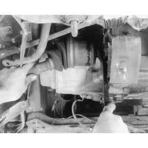
Insert a lever between the left-side driveshaft and
transaxle case
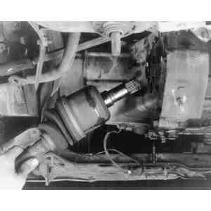
Pull the front hub outward and separate the driveshaft
from the transaxle
Remove the driveshaft locknut from the center of the brake rotor. Pull the
front hub outward and toward the rear. Disconnect the driveshaft from the
wheel hub. If necessary, use a puller. Then, pull the driveshaft straight out
of the transaxle, supporting the joint on the transaxle side to prevent damage
to the seal. Seal the transaxle opening with a clean rag.
On the right side:
Insert a lever between the joint shaft and driveshaft, then gently tap on
the outer end of the lever to separate the two shafts.
Levering the joint shaft and right-side driveshaft
apart on the 626
Remove the driveshaft locknut, then pull the front hub outward and toward
the rear. Disconnect the driveshaft from the front hub. If necessary, use a
puller. Then, disconnect the driveshaft from the cross-shaft completely.
If it is necessary to remove the cross-shaft, remove the cross-shaft
mounting bracket bolts, then remove the shaft and bracket as an assembly,
being careful not to disturb the position of differential gears. Cover the
opening in the differential case with a clean rag.
Installation is the reverse of removal, but note these points:
Check the transaxle oil seal for damage and replace it if necessary.
Replace the clips at the inner ends of the driveshaft or cross-shaft
where they are locked into the differential gears in the transaxle.
Install the shafts into the transaxle carefully to avoid damage to the
oil seal. Push the joint in on the differential side. Check the differential
gears for alignment before attempting to install the shafts. If they are not
aligned, turn them with your finger, as necessary.
After installation, pull the hub forward to make sure the driveshaft
remains locked in the transaxle.
Install a new locknut onto the outer end of the driveshaft, adjusting
wheel bearings as described in Section 8. Crimp the tabs over
after they are aligned with the groove in the driveshaft.
Tighten the stabilizer bar link nut until 1 in. (25mm) of thread is
exposed.
Torque the lower control arm-to-ball joint nut and bolt to 32-40 ft.
lbs. (43-54 Nm).
Torque the control link for the lower arm and stabilizer bar to 9-13 ft.
lbs. (12-18 Nm); except for the 1988-89 626s and MX-6s on which it should be
12-17 ft. lbs. (16-23 Nm).
Refill the differential with fresh fluid meeting proper specifications.
CV-JOINT OVERHAUL
GLC
The joint on the wheel side of the drive axle is
non-rebuildable. If worn, the joint and axle must be replaced. However, the boot
may be changed as necessary. Do not interfere with the balancer found on the
right shaft unless necessary for wheel joint boot replacement. If the balancer
is removed, it must be reinstalled in the same position (14.45 in. or 367mm from
the front of the wheel joint).
Remove the boot band by raising the locking clip and band with a pair of
pliers.
Remove the lock clip from the inner edge of the ball joint casting. Remove
the casting.
Remove the snapring from the end of the splines, then remove the cage and
bearings.
Carefully pry the balls from the bearing cage. After the balls are
removed, turn the cage slightly and remove it from the inner ring.
Wash all of the parts in a safe solvent and inspect for wear.
CV-joint overhaul parts are available in kits for serviceable
(inner) joints. Replacement boots should be available for all outer
ends.
Install the replacement parts in the reverse order of disassembly. Always
use the grease supplied with the kits. Tape the spline ends of the shaft when
installing the rubber boots.
323, 626 and MX-6
Disassemble the driveshaft (halfshaft) as shown in the exploded view. The
clip (2) should be removed with a small prytool, while the snapring (4) should
be removed with snapring pliers or a similar tool.
Pull the ball bearings, inner ring and cage out of the shaft while still
assembled. Insert an small prytool between the inner ring and cage to gently
pry each ball out. Matchmark the cage and inner ring, then turn the cage 30
degrees and pull it off the inner ring.
Assemble in the reverse order, being careful to thoroughly repack bearings
in the grease supplied with the kit.
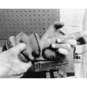
Check the CV-boot for wear or
damage
Release (or cut) the outer band from the
CV-boot
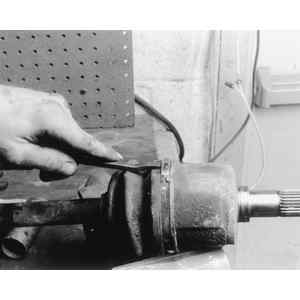
Use cutters to carefully release the inner band from
the CV-boot
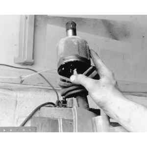
Remove the CV-boot from the joint
housing
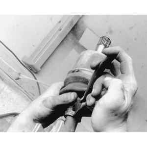
Remove the CV-joint housing assembly to access the
joint components
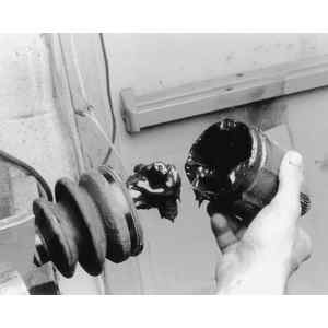
Carefully remove the CV-joint
components
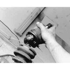
Thoroughly clean and inspect the CV-joint
housing
Remove the CV-joint outer
snapring
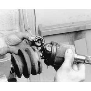
Remove the CV-joint assembly
Use a pair of snapring pliers to remove the CV-joint
inner snapring
Installing the CV-joint
assembly
Exploded view of 626 driveshaft and CV-joint; 323 and
MX-6 similar