A mechanical pump is used on all GLC models, 1983-85 626s, and
carbureted 323s. The pump is located on the right side of the engine block on
rear wheel drive models and on the left rear side of the cylinder head on most
front wheel drive models.
REMOVAL & INSTALLATION
Be sure to obtain new fuel pump gaskets before
installation.
Open the hood and disconnect the negative battery cable.
Mark the fuel inlet, outlet and (if applicable) return lines near the fuel
pump connections, to avoid confusion during installation.
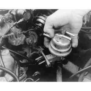
Slide the fuel line clips back off the pump connectors. Then, twist and
pull the fuel lines off the pump. Note that the 323 and 626 have inlet and
return lines on the top of the pump and an outlet on the side.
Unfasten the mounting bolts (usually two) from the block or cylinder head,
then remove the pump, gaskets, and spacer.
To install:
Position new gaskets with the spacer and fuel pump on the block or
cylinder head, then install the mounting bolts.
Attach the inlet, outlet and (if applicable) return lines to the
appropriate connections on the pump and secure them with the line clips.
Connect the negative battery cable. Start the engine and check for fuel
leaks.
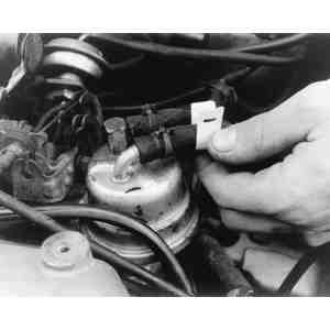
Most mechanical fuel pumps have inlet and return lines
attached at the top-626 shown; 323 similar
Before disconnecting any lines, label them for easier
installation
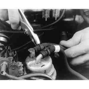
Squeeze the spring-type fuel line clips with a pliers
in order to slide them back at free the line
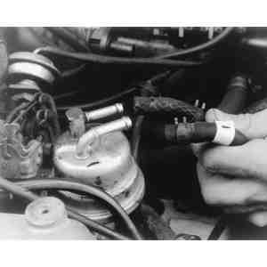
Twist and pull the fuel lines from the
pump
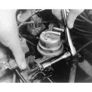
Unfasten the fuel pump's retaining
bolts
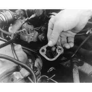
Disengage the fuel pump's actuating lever, then remove
the pump
Be sure to also remove the old gaskets and
spacer
Exploded view of mechanical fuel pump components-323
shown
TESTING
Disconnect the fuel inlet line going to the carburetor. Install a
calibrated pressure gauge into the line coming from the pump. Be careful not
to spill any fuel, but if you do, remove all spillage before starting the
engine.
Start the engine and run it at idle using the fuel still in the carburetor
float bowl. Allow the engine to run until the pressure gauge reaches a maximum
reading. Note the pressure reading. Normal specifications are 2.84-3.84 psi
(20-26 kPa), except for the 323, whose specifications are 3.98-4.98 psi
(27.4-34.3 kPa) for the Sedan or 3.91-4.93 psi (27-34 kPa) for the Wagon.
Stop the engine. Remove the pressure gauge, reinstall the fuel line into
the carburetor, and run the engine until the carburetor float bowl is full of
fuel.
To test the volume of fuel discharged by the pump, the engine must be run
at idle for one minute. Position a durable container (preferably metal) with a
capacity of at least 11/2 qts. near the carburetor fuel
inlet line. Disconnect the fuel line at the carburetor, and put the open end
into the container. Idle the engine until it stops (or for one minute) and
time how long it has run. Then, reconnect the fuel line to the carburetor and
run the starter or idle the engine until the float bowl is full. Repeat the
fuel discharge and timing operation until the engine has run for a total of
one full minute at idle speed and all the fuel discharged by the pump has been
collected. The pump must discharge at least 1.1 qts. per minute.
The pump should be replaced if it fails either the pressure or volume
test.
Electric Fuel Pump
The 1979-82 and 1986-89 626 models are equipped with an electric
fuel pump. The pump is located under the floor of the car in front of the fuel
tank.
The RX-7 is equipped with an electric fuel pump which maintains
fuel pressure at 3.7-4.7 psi (26-32 kPa). The pump is mounted near the fuel tank
and access to the pump is gained by removing the rear floor mat and the storage
compartment behind the driver's seat. The fuel pump comes on as soon as the
ignition switch is turned to the ONposition.
REMOVAL & INSTALLATION
1979-82 and 1986-89 626
Disconnect the negative battery cable.
Disconnect the fuel pump lead wire in the luggage compartment.
Raise the vehicle and support with jackstands.
Disconnect the fuel pump bracket.
Disconnect the fuel inlet and outlet hoses, then remove the fuel pump from
the bracket.
To install:
Install the fuel pump in the bracket, then connect the inlet and outlet
hoses.
Install the fuel pump mounting bracket.
Lower the vehicle and connect the fuel pump lead wire.
Connect the negative battery cable.
RX-7
Disconnect the negative battery cable.
From behind the driver's seat, remove the rear floor mat and floor plate.
Disengage the fuel pump electrical connection under the floor plate.
Raise the car and support it on jackstands.
Remove the fuel pump protecting cover. Slide the two clips from the inlet
and outlet lines, then disconnect the inlet and outlet lines from the pump.
Remove the pump from the protector.
To install:
Insert the fuel pump into the protector. Connect the fuel lines to the
pump by firmly pushing the end of each line onto the pump connection using a
twisting motion. Secure the lines with the clips.
Lock the cover onto the protector and lower the vehicle.
Engage the fuel pump connector, then replace the floor plate and floor
mat.
Connect the negative battery cable.
TESTING
Make sure the fuel filter is not clogged before testing the
fuel pump.
Remove the air cleaner assembly. Position an approved fuel container with
a capacity of at least 11/2 qts. near the carburetor
fuel inlet line.
Disconnect the carburetor fuel inlet line. Turn the ignition switch
ONand allow air to be purged from the system with the line pointed into
the container.
Connect a jumper wire to the "LW" and "BW" (center)
terminals-1984-85 RX-7
Turn the ignition OFF. Install a pressure gauge, restrictor and
length of fuel-resistant flexible hose into the line.
On 1984-85 RX-7s, unfasten the connector from the fuel pump cut relay and
connect a jumper wire as shown.
Turn the ignition ON. When the pressure has stabilized, note the
reading, then turn the ignition OFF. On 626s, the pressure should be
5.4 psi (37 kPa). On RX-7s, the pressure should be 3.7-4.7 psi (26-32 kPa) for
1979-82 models, or 2.84-3.55 psi (20-24 kPa) for 1983-85 models.
Detach the pressure gauge from the fuel line and position the line so fuel
will be discharged into the container. Turn the ignition switch ONfor
one minute. The volume should be 0.9 qts. for 1983-85 RX-7, or 1.22 qts. for
all other cars, including 1979-82 RX-7s.
If the pump fails one or both tests, replace it.
Carburetor
ADJUSTMENTS
Fast Idle
1978 GLC
This adjustment can be performed only with the carburetor
removed from the engine.
Close the choke valve fully, and measure the clearance between the lower
edge of the throttle and the throttle bore with a wire feeler gauge. The
dimension is 0.05-0.06 in. (1.2-1.5mm).
If necessary adjust by bending the rod which connects the choke shaft and
fast idle cam.
1979-85 GLC AND 1979-82 626
On the 1.4L GLC engine, remove the bimetal cover.
Using your finger close the choke valve fully.
Fast idle cam adjustment-1.4L
engine
Fast idle cam adjustment-2.0L
engine
Make sure the fast idle cam is on the 1st position (3rd position for the
1.5L GLC engine).
The throttle valve opening (clearance G) should be:
1.4L engine: 0.06 in. (1.4mm) in 1979; 0.04 in. (1.04mm) in 1980
1.5L engine: 0.03 in. (0.66mm)
2.0L engine: 0.04 in. (1.04mm) in 1979; 0.02 in. (0.61mm) for 1980-82
Adjust by turning the adjustment screw.
Turn the adjustment screw clockwise to increase the
clearance.
RX-7
To adjust the fast idle, it is necessary for the carburetor to
be removed from the car.
Remove the carburetor from the vehicle.
Fully close the check valve.
Fast idle adjustment-RX-7
Measure the clearance between the primary throttle valve and the wall of
the throttle bore. Clearances are as follows:
1979 (California) and 1980-0.05-0.06 in. (1.30-1.50mm)
1979 (49 states, Canada) and 1981-0.035-0.043 in. (0.90-1.10mm)
1982 (All models)-0.03-0.04 in. (0.8-1.0mm)
1983-85 (All models)-0.04-0.05 in. (1.0-1.2mm)
If clearance is not correct, bend the fast idle rod until proper clearance
is obtained.
Float and Fuel Level
GLC
Invert the air horn and lower the float slowly until the seat lip just
touches the needle valve. Measure the clearance between the float and air horn
gasket surface (remove the gasket). It should be 0.43 in. (11mm). Bend the
float seat lip as necessary to correct the dimension.
With air horn still inverted, lift the float upward until the float stop
contacts the air horn. Measure the clearance between the top of the needle
valve and the float seat lip. It should be 0.05-0.07 in. (1.3-1.7mm). If not,
bend the float stop until the clearance is correct.
1979-82 626
Invert the air horn and allow the float to lower by its own weight.
Measure the clearance between the float and the air horn bowl. The
clearance should be 0.43 in. (11mm). Bend the float seat lip to adjust.
Turn the air horn to the normal position and allow the float to lower by
its own weight.
Measure the distance between the bottom of the float and the air horn
bowl. The distance should be 1.8 in. (46mm). Bend the float stopper to adjust.
1983-87 626
Invert the air horn and allow the float to lower by its own weight.
Measure the clearance between the float and the air horn bowl. The
clearance should be 0.53 in. (13.5mm). Bend the float seat lip to adjust.
Float to air horn bowl adjustment (clearance
"H")-1983-87 626
Float bottom to air horn bowl adjustment (clearance
"L")-1983-87 626
Turn the air horn to the normal position and allow the float to lower by
its own weight.
Measure the distance between the bottom of the float and the air horn
bowl. The distance should be 1.93 in. (49mm). Bend the float stopper to
adjust.
1979-85 RX-7
The float bowl fuel level can be checked through the sight glass
in the carburetor body. Fuel level should be in the center of the glass. Be sure
to check the level of both float chambers.
Remove the air cleaner and remove the top part of the carburetor (the air
horn).
Turn the air horn upside down and allow the float to rest, as shown in the
illustration. Measure clearance Hbetween the float and the air horn
gasket. Clearance should be 0.61-0.65 in. (15.5-16.5mm). If clearance is not
correct, bend the float seat lip as required to adjust.
Turn the air horn to normal position and measure clearance Lbetween
the bottom of the float and the air horn gasket. Distance should be 1.99-2.03
in. (50.5-51.5mm). Adjust by bending the float stopper.
Float to air horn bowl adjustment (clearance
"H")-RX-7
Float bottom to air horn bowl adjustment (clearance
"L")-RX-7
Throttle Linkage
PISTON ENGINES
Check the accelerator pedal position; it should be lower than the brake
pedal.
If necessary, adjust the nut on the linkage above the pedal to obtain the
proper height.
Check the free-play of the cable at the carburetor. It should be 0.04-0.12
in. (1-3mm). If not, adjust by turning the clevis nut.
The accelerator pedal distance below the brake pedal should be 1.78-2.17
in. (45-55mm) for the 1983-85 GLC.
On vehicles other than 1983-85 GLCs, depress the accelerator pedal to the
floor and confirm that the throttle valve is fully open. Adjust as necessary,
by using the adjusting bolt or nut on the linkage above the accelerator pedal.
ROTARY ENGINES
To check the adjustment of the throttle linkage, remove the air
cleaner and observe the position of the two primary throttle valves when the
accelerator is fully depressed. The valves should be in a vertical (wide open)
position. When checking the throttle linkage, also make sure that the
accelerator cable does not bind or stick in its outer cable.
Measure accelerator pedal height. It should be 1.46-1.85 in. (37-47mm)
lower than the brake pedal. If not, adjust it using nut Ain the
illustration.
Throttle linkage
adjustment-RX-7
Check the free-play of the cable at the carburetor by applying light
finger pressure to the middle of the cable. It should be between 0.04-0.12 in.
(1-3mm). If not, adjust it using nut Bin the illustration.
Fully depress the accelerator pedal and check to see that the primary
throttle valves are wide open. If not, adjust stopper bolt Cin the
illustration.
Semi-Automatic Choke
1979-80 RX-7
You will need a vacuum source of more than 19.7 in. Hg. (500 mm
Hg) to make this adjustment.
Disconnect the vacuum sensing tube from the vacuum diaphragm.
Pull the choke lever link out fully and hold it in this position.
Apply vacuum to the vacuum diaphragm.
Check the clearance between the top of the choke valve and the throttle
bore body, with a wire gauge.
Measure the temperature of the bimetal spring, then compare it and the
clearance with the specifications given in the accompanying charts.
If clearance is not within specifications, adjust it by turning the
adjusting nut.
Choke valve clearance chart-1979
RX-7
Choke valve clearance chart-1980 RX-7 (49 states and
Canada)
This adjustment should be performed when the throttle body,
throttle lock lever and/or adjusting screw have been tampered with or changed.
Remove the carburetor from the engine.
Loosen the locknut and turn the adjusting screw to the left
(counterclockwise).
Close the throttle valve completely and gradually tighten the adjusting
screw until it just touches the throttle lock lever. Tighten the screw an
additional 1/8-3/8 of a turn, then
tighten the locknut.
Measure the clearance and the angle of opening for the primary throttle
valve when closed. Clearance should be 0.002 in. (0.05mm) and the angle of
opening should be 1 degree. If not, reset the throttle opening with the
adjusting screw.
Primary throttle valve adjustment-1979-80
RX-7
Automatic Choke
GLC AND 626
Fully depress the accelerator pedal to make sure the choke valve closes
properly.
Check for binding in the choke valve by pushing it with your finger.
Make sure that the bimetal cover index mark is set to the center choke
housing index mark; adjust if necessary.
Check the automatic choke heater source wiring for proper connection.
Start the engine and let it idle.
After the engine warms up, check that the choke valve is fully opened.
If the valve does not open fully, and the automatic choke heater source
wiring is normal, replace the bimetal cover.
The bimetal cover index mark should be set to the
center mark on the choke housing-GLC and 626
RX-7
Perform this check with the engine "overnight" cold.
With a cold engine and the ignition switch in the OFFposition, pull
the choke knob out fully and make sure the knob returns automatically.
Connect a tachometer to the engine.
Start the engine and use the choke knob to set the idle speed to 2,000
rpm. Allow the engine to run at this speed and observe the temperature gauge.
The choke knob should return back to its original position when the pointer on
the gauge rises to just about the low mid-range portion of the scale.
Choke Unloader
GLC AND 626
Close the choke valve fully, then open the primary throttle valve fully.
Measure the choke valve clearance. The clearance should be 0.08-0.09 in.
(2.00-2.40mm) for the GLC and 0.10-0.14 in. (2.65-3.45mm) for the 626.
Bend the tab to adjust.
Secondary Throttle Valve
GLC and 626
The secondary throttle valve starts to open when the primary throttle
valve is open 49-51 degrees, and opens completely at the same time that the
primary throttle valve is fully open.
Check the clearance between the primary throttle valve and the wall of the
throttle bore when the secondary throttle valve starts to open.
The clearance should be:
Rear wheel drive GLC hatchback: 0.21-0.26 in. (5.40-6.60mm)
Rear wheel drive GLC wagon: 0.29-0.32 in. (7.30-8.25mm)
Front wheel drive GLC-except 1982: 0.21-0.26 in. (5.40-6.60mm); 1982:
0.29-0.33 in. (7.30-8.50mm)
626: 0.24-0.28 in. (6.20-7.20mm)
To adjust the clearance, bend the connecting rod.
Secondary throttle valve adjustment-GLC and
626
Throttle Sensor
RX-7
The throttle sensor should be checked, and adjusted as necessary,
whenever the idle speed has been adjusted.
Warm up the engine to its normal operating temperature.
Connect a suitable tachometer to the engine.
Detach the brown connector, as illustrated.
Unfasten the brown wiring
connector
When adjusting the RX-7 throttle sensor, connect a pair
of voltmeters as illustrated
Using two voltmeters, connect a negative probe to each terminal (GY and
LgY) of the connector.
A two-bulb test light can be assembled (as illustrated) and
used in place of the voltmeters.
Connect the positive probe of each voltmeter to the Bterminal of
the alternator.
Start the engine.
Quickly decelerate the engine speed from 3,000 rpm and check that current
flows to both terminals simultaneously. The engine speed should be 1,000-1,200
rpm.
A two-bulb test light can be assembled and used instead
of the voltmeters
After turning the throttle sensor adjusting screw,
reposition its protective cap
If current does not start to flow to both terminals simultaneously, remove
the cap from the throttle sensor adjusting screw.
Adjust the timing of the current flowing to voltmeter A (connected to LgY)
by turning the throttle sensor adjusting screw. When the screw is turned in
(clockwise), current will begin to flow earlier; when the screw is turned out
(counterclockwise), current will begin to flow later.
When adjustment is complete, install the cap on the adjusting screw.
Remove the test equipment and fasten the brown connector.
Hot Start Assist System
When a rotary engine is hot, the best way to start it is to open
the throttle fully. To save the driver from this task, Mazda has equipped the
RX-7 with a hot start assist motor which opens the throttle while engaging the
starter on a warm engine. The motor is mounted on the left side of the engine
compartment and is attached to the carburetor linkage by a cable. The system can
be easily checked as follows: with the engine warm, open the hood and have an
assistant watch the cable at the hot start assist motor while you engage the
starter. The cable should pull back while the starter is engaged and release as
soon as the starter is disengaged. If the cable requires adjustment, proceed as
follows:
1979-83 RX-7
Remove the lock spring on the cable bracket.
Slowly pull the outer cable until the hot start lever just touches the
stopper lever. Check the clearance between the cable bracket and the locknut
of the cable. Clearance should be 0.05 in. (1.25mm). Adjust the clearance by
turning the locknut.
Install the lock spring.
1984-85 RX-7
Pull the start assist motor inner cable until the stopper lever makes
contact with the start lever and check the free-play; it should be 0.04-0.08
in. (1-2mm).
If the free-play is not as specified, loosen the screw and adjust it.
Hot start assist cable adjustment-1979-83
RX-7
Hot start assist cable adjustment-1984-85
RX-7
REMOVAL & INSTALLATION
Piston Engines
Disconnect the negative battery cable.
Remove the air cleaner assembly.
Disconnect the accelerator cable. If equipped, disconnect the cruise
control cable.
Disengage all wire connections, vacuum sensing tubes and fuel hoses.
Unfasten and remove the carburetor. Cover the opening to keep dirt out of
the intake manifold.
Installation is the reverse of removal. Be sure to use a new carburetor
gasket. Adjust the throttle linkage as previously described.
Rotary Engines
The RX-7 is equipped with a 4-barrel carburetor which is similar
in design to the carburetors used on piston engines. Two primary barrels feed a
constant mixture of air and fuel to the rotors. The primary barrels are
supplemented by two vacuum operated secondary barrels during acceleration and
high speed driving.
Disconnect the negative battery cable.
Remove the air cleaner assembly.
Label and unfasten all electrical connections from the carburetor and
necessary surrounding components.
Label and disconnect all necessary vacuum hoses.
Disconnect the oil metering pump linkage at the carburetor.
Disconnect the hot start assist cable, along with the choke and
accelerator cables, from the carburetor. Route the cables off to the side and
out of the way.
Disconnect the air vent hose. On all except California vehicles,
disconnect the sub-zero start assist fluid hose.
Disconnect the fuel return and the main fuel hoses. Plug the main fuel
line to prevent leakage.
Disconnect the metering oil pump lines from the carburetor. Disconnect the
air vent solenoid valve coupler.
Remove the carburetor attaching nuts and remove the carburetor. Cover the
intake manifold with masking tape to prevent dirt and debris from entering the
engine. Discard the old gasket; a new one should be used during assembly to
assure proper vacuum seal.
To install:
Place the new gasket onto the intake manifold, then install the carburetor
over the mounting studs and onto the gasket.
Install and tighten the attaching nuts.
Complete the remainder of the installation in reverse of the removal
procedure. Adjust the throttle linkage as previously described.
Connect the negative battery cable.
Carburetor removal-RX-7
OVERHAUL
Carburetor rebuilding kits usually include specific procedures and
exploded views for order of assembly and disassembly, therefore, only general
applicable rebuilding suggestions are provided here. Efficient carburetion
depends greatly on careful cleaning and inspection during overhaul since dirt,
gum, water, or varnish in or on the carburetor parts are often responsible for
poor performance.
Overhaul your carburetor in a clean, dust-free area. Carefully
disassemble the carburetor, referring often to the exploded views. Be sure to
keep all similar/look-alike parts segregated during disassembly and cleaning to
avoid accidental interchange during assembly. Make a note of all jet sizes.
When the carburetor is disassembled, wash all parts (except
diaphragms, electric choke units, pump plunger, and any other plastic, leather,
fiber, or rubber parts) in clean carburetor solvent. Do not leave parts in the
solvent any longer than is necessary to sufficiently loosen the deposits.
Excessive cleaning may remove the special finish from the float bowl and choke
valve bodies, leaving these parts unfit for service. Rinse all parts in clean
solvent and blow them dry with compressed air or allow them to air dry. Wipe
clean all cork, plastic, leather, and fiber parts with a clean, lint-free cloth.
Blow out all passages and jets with compressed air; be sure that
there are not restrictions or blockages. Never use wire or similar tools to
clean jets and valves. Also, be sure to clean all jets and valves separately to
avoid accidental interchange.
Check all parts for wear or damage; replace all defective parts.
During inspection, pay careful attention to the following:
Check the float needle and seat for wear. If wear is found, replace the
complete assembly.
Check the float hinge pin for wear and check the float(s) for dents or
distortion. Replace the float if fuel has leaked into it.
Check the throttle and choke shaft bores for wear or an out-of-round
condition. Damage or wear to the throttle arm, shaft, or shaft bore will often
require replacement of the throttle body. These parts require a close
tolerance of fit; wear may allow air leakage, which could affect starting and
idling.
Throttle shafts and bushings are not usually included in
overhaul kits, but they can often be purchased separately.
Inspect the idle mixture adjusting needles for burrs or grooves. Any such
condition requires replacement of the needle, since you will not be able to
obtain a satisfactory idle.
Test the accelerator pump check valves. They should pass air one way but
not the other. Test for proper seating by blowing and sucking on the valve.
Replace the valve if necessary. If the valve is satisfactory, wash the valve
again to remove breath moisture.
Check the bowl cover for warped surfaces with a straightedge.
Closely inspect the valves and seats for wear and damage, replacing as
necessary.
After the carburetor is assembled, check the choke valve for freedom of
operation.
Carburetor overhaul kits are recommended for each overhaul. These
kits contain all gaskets and new parts to replace those that deteriorate most
rapidly. Failure to replace all parts supplied with the kit (especially gaskets)
can result in poor performance later.
Some carburetor manufacturers supply overhaul kits of three basic
types: minor repair; major repair; and gasket kits. Basically, they contain the
following:
Minor Repair Kits:
All gaskets
Float needle valve
Volume control screw
All diaphragms
Spring for the pump diaphragm
Major Repair Kits:
All jets and gaskets
All diaphragms
Float needle valve
Volume control screw
Pump ball valve
Main jet carrier
Float
Complete intermediate rod
Intermediate pump lever
Complete injector tube
Some cover hold-down screws and washers
Gasket Kits
All gaskets
After cleaning and checking all components, reassemble the
carburetor, using new parts and referring to the exploded view. When
reassembling, make sure that all screws and jets are tight in their seats, but
do not overtighten, as the tips could be distorted. Tighten all screws
gradually, in rotation. Do not tighten needle valves into their seats; uneven
jetting will result. Always use new gaskets. Be sure to adjust the float level
when reassembling.