
Disconnect the high tension lead from the ignition coil
at the distributor cap
Most of the vehicles covered by this manual use an electronic ignition system in place of the old breaker point system. The electronic systems used on vehicles covered by this manual come in two basic forms: with and without distributor. Although, just like the breaker point systems, the distributors used on rotary engines is significantly different from those found on piston engines.
The electronic distributor systems replace the contact points (used in traditional breaker point systems) with an electromagnetic generator. The generator consists, in part, of a rotating pole piece (reluctor or signal rotor) on the distributor shaft and a stationary pickup coil. As the pole piece passes the pickup coil, current is generated, much as in the car's main electrical system alternator. Spikes of current are produced as each of the four corners on the pole piece pass the pickup coil and operate transistors in the igniter mounted on the coil. This provides the switching actions ordinarily handled by the contact points, but without the arcing and stress of opening and closing associated with point operation.
All 1980-85 RX-7 models are equipped with electronic distributor ignition systems which replace the conventional breaker points and condensers used in the 1979 RX-7. In place of the two sets of breaker points used in 1979 models, two pickup coils (leading and trailing) are found inside the distributor on 1980-85 models. In place of the rubbing block cam found on the distributor shaft of point-equipped models, is a four-spoked wheel called a signal rotor. Other parts of the system include the igniter, the two ignition coils and all attaching wires. When each of the spokes on the signal rotor passes in front of one of the pickup coils, it creates a signal. The pickup coil then sends this signal to the igniter and the appropriate ignition coil. This signal causes the magnetic field in the coil to collapse, creating the spark which the distributor cap passes on to the spark plug. As with the 1979 breaker point system, there is a leading and a trailing spark plug. The leading plug fires first, followed (after about 10 degrees of distributor shaft rotation) by the trailing plug, which ignites any remaining air/fuel mixture in the combustion chamber.
The 1986-89 RX-7 models utilize a distributorless ignition system, in which the distributor has been eliminated in favor of a crank angle sensor (for crankshaft position information) and ignition coils which fire the spark plugs directly from their own towers. For more information on the crank angle sensor, please refer to Section 3 of this manual.
There are several checks, unique to the electronic ignition system, which can be made to locate or repair trouble. The gap between the pole piece and pickup coil can be checked and adjusted, and the electrical resistance of the pickup coil can be checked on most vehicles built through 1982. Although it can be checked, the gap is non-adjustable on the RX-7. The resistance of the ignition coil(s) can be checked on all electronic ignition equipped vehicles.
Unplug the primary ignition wire connector, then insert an ohmmeter between the two prongs of the connector on the distributor side. The resistance of the pickup coil should be 670-790 ohms (GLC) or 720-1,050 ohms (626), as measured at room temperature. If resistance is out of range, replace the pickup coil.
For ignition coil resistance test procedures, please refer to Section 3 of this manual.
|
|
Disconnect the high tension lead from the ignition coil
at the distributor cap |
| CAUTION |
|
A properly operating secondary ignition system can
produce enough voltage to give you a nasty shock. Be sure to wrap an
insulating cloth around any high tension leads, before grasping them with
the engine running or cranking. Better yet, carefully hold the wire using
a rubber insulated tool. |
If no spark or an inadequate one is produced, and the coil tests out okay, the igniter and pickup coil may require replacement. However, you should make sure before doing this work that there are no basic maintenance problems in the secondary circuit of the system, since it is often impossible to return electrical parts. We suggest that before you replace the igniter and pickup coil, you carefully inspect the cap and rotor for carbon tracks or cracks, and also check the condition of the high tension wires. Check for cracks in the insulation and measure the resistance of the spark plug wires with an ohmmeter, as described earlier in this section. Resistance should be 16,000 ohms per 3.28 feet (1 meter). Replace secondary parts as inspection/testing deems necessary before replacing the igniter and pickup coil.
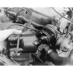
The air gap (between the signal rotor and pickup coil when one of the rotor spokes is lined up with the pickup coil) can be measured with a feeler gauge.
Air gap is checked in the same manner as for the other Mazda engines described earlier, but is not adjustable. If the air gap is not within 0.020-0.035 in. (0.5-0.9mm), the only way to correct it is to replace the entire pickup coil base/bearing assembly or the distributor driveshaft. Checking the air gap should not be considered a routine tune-up procedure.
 |
|
Unfasten the retaining screws and remove the
distributor cap |
 |
|
Unfasten and remove the rotor |
 |
|
Measuring the air gap on 1979-82 electronic ignition
systems |