Raise the back end of the car and support it with jackstands.
Remove the lug nuts and the wheel.
Support the rear axle housing with jackstands.
Disconnect the lower part of the shock from the spring clamp. Unfasten the
nuts which secure the U-bolt. Withdraw the U-bolt seat, rubber pad, plate, and
the U-bolt itself.
Unfasten the two bolts and the nut that secure the spring pin to the front
end of the rear spring.
Pry the spring pin out with a large, flat pry bar inserted between the
spring pin and its body bracket.
Remove the nuts and the bolts which attach the rear shackle to the car's
body.
Withdraw the rear spring assembly, complete with its shackle.
Remove the shackle assembly from the end of the spring.
Pull the rubber bushings out from both ends of the spring.
When installing the rubber bushings, do not lubricate them. Tighten the
U-bolt securing nuts to 30 ft. lbs., and both the spring pin and the shackle
pin to 14 ft. lbs.
GLC and 1983-89 626
Rear coil spring removal is performed as part of the shock
absorber removal operation. See the appropriate following section for the
combined procedure.
1979-82 626
Raise the rear end of the vehicle and support it with jackstands. Place
the jackstands under the bracket on the front sides of the lower arms.
Remove the rear wheel.
Place a jack under the rear axle housing to support it.
Remove the shock absorber lower attaching nut and disengage the shock
absorber form the rear axle housing.
Remove the lateral rod from the right side of the axle housing.
Remove the upper link attaching nut from the rear of the axle housing.
Remove the lower arm attaching nut from the rear axle housing.
Remove the control rod attaching nut and remove the bushings, spacer and
washers. Disengage the rear stabilizer bar from the control rod if so
equipped.
Slowly lower the jack to relieve the spring pressure on the lower arm,
then remove the spring.
During installation of the coil spring, make sure the open end of the
spring faces the rear axle housing. Tighten all bolts temporarily then after
the vehicle is lowered to the ground torque to specifications. Upper link and
lower arm to axle housing, 66 ft. lbs., Lateral rod to axle housing, 66 ft.
lbs.
1979-85 RX-7
Rear coil spring removal on 1986-89 RX-7 is performed as part
of the shock absorber removal operation. See the appropriate following section
for the combined procedure.
Raise the rear of the vehicle and support it on jackstands. Remove the
rear wheel. Support the rear axle under the differential housing with a floor
jack.
Do not place the jackstands under the rear axle assembly. See
the end ofSection 1 for proper placement.
Disconnect the lower shock absorber mounting bolt. Disconnect the upper
link and the lower link where they attach to the rear axle assembly.
Disconnect the stabilizer bar front ends (if equipped with a stabilizer
bar).
Disconnect the right and left watt links at the rear axle housing.
Carefully lower the rear axle housing on the floor jack just enough to
remove the coil springs.
Install the coil spring with the painted mark on the coils positioned
closer to the rear axle casing than to the upper spring mount.
Rear suspension components-1979-85
RX-7
Install the stabilizer bar ends as shown-1979-85
RX-7
Connect the ends of the stabilizer bar and tighten the nuts until 0.17 in.
(4.3mm) of the bolt threads protrude from the nut.
When installing the shock absorber on the left-hand side, install the
lower side attaching bolts with the bolt heads facing toward the inside.
Install the rear bolt for each upper link with the bolt heads facing toward
the inside of the car.
When installing all components, temporarily tighten all fasteners, lower
the car and tighten all fasteners fully. Observe the following torques:
Upper and lower links to bracket: 56-76 ft. lbs.
Watt link-to-rear axle: 47-59 ft. lbs. (64-80 Nm)
Rear shock absorber lower mount: 47-59 ft. lbs. (64-80 Nm)
Shock Absorbers
REMOVAL & INSTALLATION
Rear Wheel Drive GLC
Raise the rear of the vehicle and support securely via the frame side
rails. Remove the wheels.
Remove the upper shock absorber bolt from inside the fender well.
Remove the lower shock bolt and nut, then remove the shock.
To remove the rear spring, support the lower control arm with a jack.
Remove the pivot bolt which connects the lower control arm and rear axle.
Very slowly lower the jack until the spring pressure has been relieved,
and remove the spring.
Install the spring in reverse order of removal, but do not fully tighten
the pivot bolt. Then, lower the vehicle until it is at normal ride height and
torque the bolt to 47-59 ft. lbs. (64-80 Nm).
Front Wheel Drive GLC
Remove the side trim panels form inside the trunk. Loosen and remove the
top mounting nuts from the shock absorber assembly.
Loosen the rear wheel lugs, raise the car and safely support it on
jackstands.
Remove the rear wheels. Disconnect the flexible brake hose from the strut.
Disconnect the trailing arm from the lower side of the strut. Separate the
lateral link and strut by removing the bolt assembly.
Remove the strut from the lower unit by removing the two through nuts and
bolts.
Remove the strut, and brake assembly. Clamp the strut assembly in a vise
and loosen the nut at the top of the shock absorber.
CAUTION
Do not remove the nut at this
time.
Compress the coil spring with a compressor tool. Remove the top nut and
bracket. Remove the coil spring.
After mounting the strut assembly, lower the car to the ground and torque
the mountings; Piston rod and mounting block: 41-60 ft. lbs. Mounting block
and tower mount: 16-20 ft. lbs. Lower mounts: 40-50 ft. lbs.
1979-82 626
Raise the rear end of the vehicle and place jackstands under the bracket
on the front side of the lower arms.
Remove the rear wheel.
Remove the bracket attaching nuts from the upper end of the shock
absorber.
Remove the lower shock absorber retaining nut and remove the shock
absorber.
CAUTION
Do not disassemble the gas sealed type shock absorber
as it contains highly compressed gas. Defective shocks should be
replaced.
During installation, torque the upper bracket bolts to 28 ft. lbs., the
lower bracket bolts to 32 ft. lbs., and the shock absorber attaching nuts to
53 ft. lbs.
1983-87 626
Jack up the rear of the vehicle and support the crossmember with safety
stands.
Remove the bolts and nuts attaching the lower end of the strut to the
knuckle spindle, then carefully lower the suspension arm. Remove the brake
hose clip from the lower end of the strut. Support the strut from underneath.
Remove the rear seat and trim. Remove the attaching nut and washer on
either side the strut tower. Now, remove the support and remove the strut from
the car.
Clamp the shock gently in a vise, using soft metal plates on either side
to protect the shock tube from distortion. Keep the piston rod of the shock
from turning while using a box wrench to carefully loosen the nut on the
piston rod only enough for it to reach the top of the threads. The nut must
remain securely fastened because the spring pressure is still dangerous.
Use two clamps designed for this purpose to compress the spring, one on
either side. When the spring is securely compressed so there is no tension on
the spring seat, remove the nut, washer, and mounting block and spring seat.
Also remove the dust boot, spring, and stop. You can now replace the shock or
have it rebuilt.
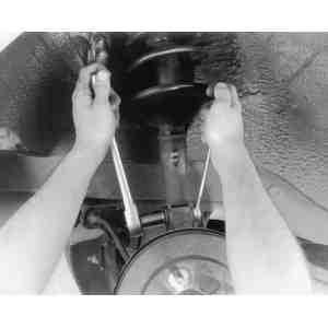
Use two wrenches to unfasten the lower end of the strut
(shock absorber) from the knuckle spindle
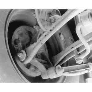
Compressing the rear spring on a front wheel drive 626.
Although Mazda part numbers are shown, an equivalent tool may be used, but
it must be designed specifically for this job
If you're replacing the spring, make sure to release the clamps carefully
and gradually before attempting to remove them. Also, be sure to clamp the new
spring adequately for it to be installed safely. Make sure the spring is
properly seated top and bottom and that the seat, block, washer, and nut are
secure before releasing spring tension.
Once the spring tension is held by the nut at the top of the unit, torque
it to 47-59 ft. lbs. (64-80 Nm). Torque the mounting block installation nuts
located behind the rear seat to 17-21 ft. lbs. (23-28 Nm), and the bolts
fastening the lower end of the strut to the knuckle spindle to 69-86 ft. lbs.
(93-117 Nm).
1988-89 626 and MX-6
Jack up the rear of the vehicle and support the crossmember with safety
stands.
Remove the rear wheels. Release the U-shaped clip from the lower shock
absorber mounting bracket and move the brake line out of the way. On vehicles
equipped with ABS, disconnect the ABS wiring harness and mounting bracket from
the lower portion of the shock absorber.
Release the trunk side trim fasteners and carefully pull the trim forward
to reveal the upper portion of the shock absorber.
On vehicles equipped with AAS, disconnect the connector from the AAS
actuating unit on top of the spring. Loosen the screws and remove the
actuating unit.
On vehicles equipped with 4WS, disconnect the strut bar from the forked
strut bar bracket by removing the bolt and lockwasher. Unfasten the nuts and
remove the bracket from the spring mounting block.
Remove the nuts from the mounting block. Remove the lower shock mounting
bolts and remove the shock absorber assembly from the vehicle.
Disassembly of the rear shock absorber is basically the same as described
in Steps 4-6 of the 1983-87 626 procedure. The only step that you will have to
add is if your vehicle is equipped with AAS. After the coil spring is removed,
use needle nose pliers to check the rotation of the AAS actuating rod. The rod
should turn freely. During installation, torque the upper shock absorber nuts
to 34-36 ft. lbs. and lower mounting bolts to 69-86 ft. lbs. (93-117 Nm). If
equipped with AAS, torque the actuating unit retaining screws to 22-31 inch
lbs. (2.5-3.5 Nm).
323
Jack up the rear of the vehicle and support it with safety stands. On
1988-89 vehicles equipped with AAS, peel the rubber cover from the actuating
unit and disengage the electrical connector. Unbolt the actuating unit from
the mounting block.
On 1986-87 323s, compress the coil spring by using the coil spring holders
49 0223 640B and 49 0370 641, then remove the nut at the upper end of the
piston rod.
Remove the bolts and nuts attaching the lower end of the strut to the rear
suspension arm, and carefully lower the arm. Remove the brake hose clip from
the lower end of the strut and move the brake hose out of the way. Support the
strut from underneath.
Remove the nuts from the top of the spring mounting block, then remove the
shock absorber assembly.
Remove the nut and washer that secure the shock absorber to the mounting
block, then remove the mounting block, spring seat and dust boot. Then remove
the bound stopper and the coil spring.
When installing the spring, check that the spring is well seated in the
upper and lower seats. When installing the mounting block on the vehicle, make
sure that the white point is to the inside of the vehicle. Torque the upper
mounting nuts to 17-22 ft. lbs. (23-30 Nm) and the lower mounting bolts to
45-50 ft. lbs (2WD) and 58-86 ft. lbs. (4WD). If equipped with ASA, torque the
actuating unit retaining bolts to 14-21 ft. lbs. (19-28 Nm).
929
Jack up the rear of the vehicle and support it with safety stands. Remove
the rear wheels.
On vehicles equipped with AAS, remove the seal plate from the actuating
unit and disengage the electrical connector.
Remove the upper mounting nuts and remove the lower mounting bolt and
lockwasher.
Install the shock with the lower mounting bolt and upper mounting nuts.
Torque the lower bolt to 54-69 ft. lbs. (73-93 Nm) and the upper nuts to 17-22
ft. lbs. (23-30 Nm).
Connect the AAS actuating unit connector and install the seal plate.
Install the rear wheels and lower the vehicle.
1979-85 RX-7
Coil spring removal and installation for 1979-85 models is
addressed separately in the preceding "Coil Spring" section. On 1986-89 RX-7s,
the coil and shock absorber are one assembly.
Raise the rear of the car and support it on jackstands.
Remove the rear wheel(s).
Open the luggage compartment hatch and remove the side trim from over the
upper shock absorber mounts.
Disconnect the upper shock absorber mounts.
Remove the bolts holding the shock absorber lower ends and remove the
shock absorbers.
Maneuver the right shock into position and tighten the lower shock
mounting bolt to 47-59 ft. lbs. (64-80 Nm).
Tighten the upper mounts on the shock absorbers so that 0.32 in. (8.2mm)
of thread protrudes from the nut as illustrated.
Install the upper shock mount as shown-1979-85
RX-7
When installing the left side shock absorber, install the lower mounting
bolt with its head toward the inside.
Install the rear wheels and lower the vehicle.
1986-89 RX-7
Removal and installation of the rear shock absorber is the same as
for previous RX-7s, except that on 1986-89 models, the coil and shock absorber
are combined as one unit.
BOUNCE TEST
Each shock absorber can be tested by bouncing the corner of the
vehicle until maximum up and down movement is obtained. Release the car; it
should stop bouncing after one or two bounces. Compare both front corners or
both rear corners, but do not compare the front to the rear. If one corner
bounces longer than the other, it should be inspected for damage; replace the
shock if necessary.
Rear Wheel Bearings
The procedures described here apply only to front wheel drive
vehicles. For rear wheel bearing replacement on rear wheel drive vehicles,
please refer to"Rear Axle; Axle Shaft, Bearing and
Seal".
REPLACEMENT
On 1988-89 626 and MX-6, a number of special tools are required
to remove the rear wheel bearing. Determine the availability of these tools
before attempting to service the rear wheel bearings.
Raise and support the vehicle safely. Remove the tire and wheel assembly.
Remove the rear brake drum or rotor and lift out the bearing cage
assembly. Remove the bearing retainer as required. Never reuse the old wheel
bearings. On 1988-89 626 and MX-6, use special tools 49-G033-102, 49-G026,
101, 49-G026-103 to drive the bearing out of the rotor disc.
Use a blunt drift to knock the bearing race out, then press in a new race
using a bench press and suitable mandrel. Tap until the race is fully seated
in the hub.
Pack the new bearing with a suitable lithium disulfide grease (NGLI No. 2
or is equivalent) and drive it into the drum or rotor. On 1988-89 626s and
MX-6s, special tools 49-G030-797, 49-G026-102 and 49-H026 or equivalent will
be required to install the bearing. Install the bearing retainer, if so
equipped. Replace the oil seal.
Complete the installation of the brake drum or rotor in the reverse of the
removal procedure. Adjust the bearing preload.
Stabilizer Bar
REMOVAL & INSTALLATION
Raise and support the rear end on jackstands.
Remove the bolts (along with the bushings, retainers and spacers) which
fasten the stabilizer bar to the lateral links.
Each end of the stabilizer bar is fastened to a front
lateral link-1984 626 shown
Unfasten and remove the retaining bushings and brackets.
Remove the stabilizer bar.
Inspect all parts for wear or damage and replace any suspect parts.
Installation is the reverse of removal. Install all fasteners hand-tight,
then lower the vehicle to the ground. With the weight of the vehicle on the
wheels, tighten the retaining bushing bracket fasteners to 38 ft. lbs. (51
Nm). Tighten the lateral link bolts until 0.59 (15mm) of thread is visible
above the nut.
Rear End Alignment
Due to the complex nature of rear alignment procedures and the
equipment needed to perform them, it is best that such an adjustment be referred
to an alignment specialist.